292
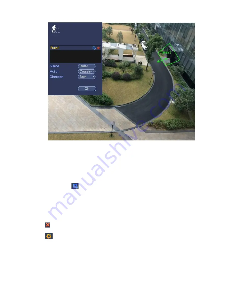
Figure 4-130
Select direction, and then input customized rule name.
Preset: Select a preset you want to use behavior analytics.
Name: Input customized rule name.
Direction (A
→
B/B
→
A/A
↔B): System can generate an alarm once there is any object crossing in the
specified direction.
Target filter: Click
, you can set filter object size. Each rule can set two sizes (min size/max size).
Once the object is smaller than the min size or larger than the max size, there is no alarm. Please
make sure the max size is larger than the min size.
Now you can draw a rule. Left click mouse to draw a warning zone. Right click mouse to complete the
setup.
Tips
Click
to delete the corresponding rule.
Click
, y
ou can refer to chapter 4.7.4.1 to set other parameters.
Click Apply to complete the setup.
4.7.4.3 Abandoned Object Detect (Optional)
System generates an alarm when there is abandoned object in the specified zone.
From main menu->Setting->Event->Behavior analytics, select the type as abandoned object, the object
interface is shown as below. See Figure 4-131.
Содержание NVR-ELE4ME-WS
Страница 1: ...1080p Resolution 1yr Warranty Motion Activated Recording PTZ Control View From Anywhere NVR ELE4ME WS...
Страница 33: ...163 Figure 3 3 3 5 4 Compact 1U Series Please refer to Figure 3 4 for connection sample...
Страница 34: ...164 Figure 3 4 3 5 5 Compact 1U Wireless Series Please refer to Figure 3 5 for connection sample...
Страница 43: ...173 Figure 3 16 3 5 17 Professional 1 5U Series Please refer to Figure 3 17 for connection sample...
Страница 45: ...175 Figure 3 18 3 5 19 Professional 2U Series Please refer to Figure 3 19 for connection sample...
Страница 47: ...177 Figure 3 20 3 5 21 Professional 2U with RAID series Please refer to Figure 3 21 for connection sample...
Страница 48: ...178 Figure 3 21 3 5 22 Professional 3U Series Please refer to Figure 3 22 for connection sample...
Страница 50: ...180 Figure 3 23 3 5 24 Beneficio Vertical 1U Series Please refer to Figure 3 24 for connection sample...
Страница 51: ...181 Figure 3 24...
Страница 63: ...193 Figure 4 14 Figure 4 15 Step 2 Set network camera login password WARNING...
Страница 71: ...201 Figure 4 24 Step 2 Click device display edit interface See Figure 4 25...
Страница 148: ...278 Figure 4 114 Figure 4 115...
Страница 159: ...289 Figure 4 126 Figure 4 127...
Страница 161: ...291 Figure 4 129 Click draw button to draw the zone See Figure 4 130...
Страница 165: ...295 Figure 4 133 Click Draw button to draw a zone See Figure 4 134 Figure 4 134...
Страница 170: ...300 Figure 4 139 Click draw button to draw the zone See Figure 4 140...
Страница 183: ...313 Figure 4 151 Figure 4 152...
Страница 184: ...314 Figure 4 153 Figure 4 154...
Страница 214: ...344 Figure 4 189 In Figure 4 189 click one HDD item the S M A R T interface is shown as in Figure 4 190 Figure 4 190...
Страница 250: ...380 Figure 4 236...
Страница 294: ...424 Figure 5 60 Figure 5 61...
Страница 295: ...425 Figure 5 62 Figure 5 63...
Страница 319: ...449 Figure 5 97 Figure 5 98...
Страница 322: ...452 Figure 5 101 Figure 5 102...


