440
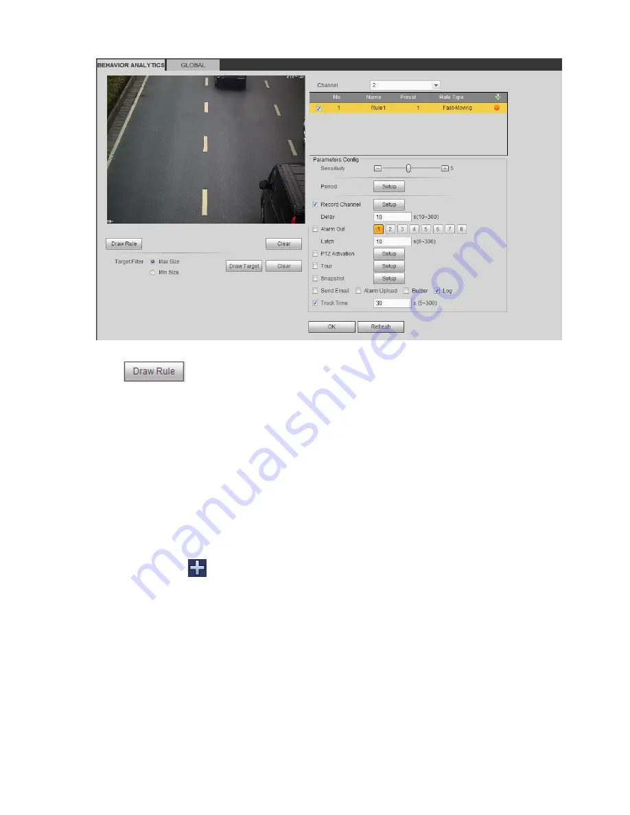
Figure 5-84
Click
to draw the rule.
Click OK to complete the rule setup.
For detailed setups, please refer to chapter 5.10.3.1.1 motion detect for detailed information.
5.10.3.3.2 Global Config
From main menu->Setup->Event->Behavior analytics->Global, you can go to the global configuration
interface. See Figure 2-32.
Channel: Please select a channel from the dropdown list.
Preset: Select a preset you want to set the rule. Please note, you need to add a preset first,
otherwise, you cannot see the preset dropdown list. If there is no preset, you can draw a rule in
current channel.
Calibration zone:
Click Add area
, you can draw a calibration zone at the left pane of the interface. Select a zone
and then click Delete zone button; you can remove the selected zone.
Select gauge type (vertical/level), you can set the corresponding length. You can draw three tilt
gauges and one horizontal gauge at the left pane of the interface.
Select Width/Height and then click Verify, you can draw a line in the calibration zone, and then you
can see its actual length.
Update preset: Click it to get the latest preset setup.
Содержание NVR-ELE4ME-WS
Страница 1: ...1080p Resolution 1yr Warranty Motion Activated Recording PTZ Control View From Anywhere NVR ELE4ME WS...
Страница 33: ...163 Figure 3 3 3 5 4 Compact 1U Series Please refer to Figure 3 4 for connection sample...
Страница 34: ...164 Figure 3 4 3 5 5 Compact 1U Wireless Series Please refer to Figure 3 5 for connection sample...
Страница 43: ...173 Figure 3 16 3 5 17 Professional 1 5U Series Please refer to Figure 3 17 for connection sample...
Страница 45: ...175 Figure 3 18 3 5 19 Professional 2U Series Please refer to Figure 3 19 for connection sample...
Страница 47: ...177 Figure 3 20 3 5 21 Professional 2U with RAID series Please refer to Figure 3 21 for connection sample...
Страница 48: ...178 Figure 3 21 3 5 22 Professional 3U Series Please refer to Figure 3 22 for connection sample...
Страница 50: ...180 Figure 3 23 3 5 24 Beneficio Vertical 1U Series Please refer to Figure 3 24 for connection sample...
Страница 51: ...181 Figure 3 24...
Страница 63: ...193 Figure 4 14 Figure 4 15 Step 2 Set network camera login password WARNING...
Страница 71: ...201 Figure 4 24 Step 2 Click device display edit interface See Figure 4 25...
Страница 148: ...278 Figure 4 114 Figure 4 115...
Страница 159: ...289 Figure 4 126 Figure 4 127...
Страница 161: ...291 Figure 4 129 Click draw button to draw the zone See Figure 4 130...
Страница 165: ...295 Figure 4 133 Click Draw button to draw a zone See Figure 4 134 Figure 4 134...
Страница 170: ...300 Figure 4 139 Click draw button to draw the zone See Figure 4 140...
Страница 183: ...313 Figure 4 151 Figure 4 152...
Страница 184: ...314 Figure 4 153 Figure 4 154...
Страница 214: ...344 Figure 4 189 In Figure 4 189 click one HDD item the S M A R T interface is shown as in Figure 4 190 Figure 4 190...
Страница 250: ...380 Figure 4 236...
Страница 294: ...424 Figure 5 60 Figure 5 61...
Страница 295: ...425 Figure 5 62 Figure 5 63...
Страница 319: ...449 Figure 5 97 Figure 5 98...
Страница 322: ...452 Figure 5 101 Figure 5 102...


