337
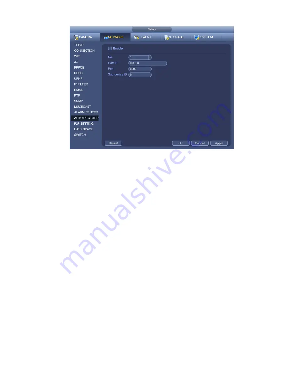
Figure 4-181
2) The proxy server software developed from the SDK. Please open the software and input the global
setup. Please make sure the auto connection port here is the same as the port you set in the previous
step.
3) Now you can add device. Please do not input default port number such as the TCP port in the mapping
port number. The device ID here shall be the same with the ID you input in Figure 4-181. Click Add button
to complete the setup.
4) Now you can boot up the proxy server. When you see the network status is Y, it means your
registration is OK. You can view the proxy server when the device is online.
Important
The server IP address can also be domain. But you need to register a domain name before you run proxy
device server.
4.8.1.16 P2P
You can use your cell phone to scan the QR code and add it to the cell phone client.
Via the SN from scanning the QR code, you can access the device in the WAN. Please refer to the P2P
operation manual included in the resources CD.
From main menu->Setting->Network->P2P, you can go to the following interface, the P2P interface is
shown as in Figure 4-182.
Содержание NVR-ELE4ME-WS
Страница 1: ...1080p Resolution 1yr Warranty Motion Activated Recording PTZ Control View From Anywhere NVR ELE4ME WS...
Страница 33: ...163 Figure 3 3 3 5 4 Compact 1U Series Please refer to Figure 3 4 for connection sample...
Страница 34: ...164 Figure 3 4 3 5 5 Compact 1U Wireless Series Please refer to Figure 3 5 for connection sample...
Страница 43: ...173 Figure 3 16 3 5 17 Professional 1 5U Series Please refer to Figure 3 17 for connection sample...
Страница 45: ...175 Figure 3 18 3 5 19 Professional 2U Series Please refer to Figure 3 19 for connection sample...
Страница 47: ...177 Figure 3 20 3 5 21 Professional 2U with RAID series Please refer to Figure 3 21 for connection sample...
Страница 48: ...178 Figure 3 21 3 5 22 Professional 3U Series Please refer to Figure 3 22 for connection sample...
Страница 50: ...180 Figure 3 23 3 5 24 Beneficio Vertical 1U Series Please refer to Figure 3 24 for connection sample...
Страница 51: ...181 Figure 3 24...
Страница 63: ...193 Figure 4 14 Figure 4 15 Step 2 Set network camera login password WARNING...
Страница 71: ...201 Figure 4 24 Step 2 Click device display edit interface See Figure 4 25...
Страница 148: ...278 Figure 4 114 Figure 4 115...
Страница 159: ...289 Figure 4 126 Figure 4 127...
Страница 161: ...291 Figure 4 129 Click draw button to draw the zone See Figure 4 130...
Страница 165: ...295 Figure 4 133 Click Draw button to draw a zone See Figure 4 134 Figure 4 134...
Страница 170: ...300 Figure 4 139 Click draw button to draw the zone See Figure 4 140...
Страница 183: ...313 Figure 4 151 Figure 4 152...
Страница 184: ...314 Figure 4 153 Figure 4 154...
Страница 214: ...344 Figure 4 189 In Figure 4 189 click one HDD item the S M A R T interface is shown as in Figure 4 190 Figure 4 190...
Страница 250: ...380 Figure 4 236...
Страница 294: ...424 Figure 5 60 Figure 5 61...
Страница 295: ...425 Figure 5 62 Figure 5 63...
Страница 319: ...449 Figure 5 97 Figure 5 98...
Страница 322: ...452 Figure 5 101 Figure 5 102...


