318
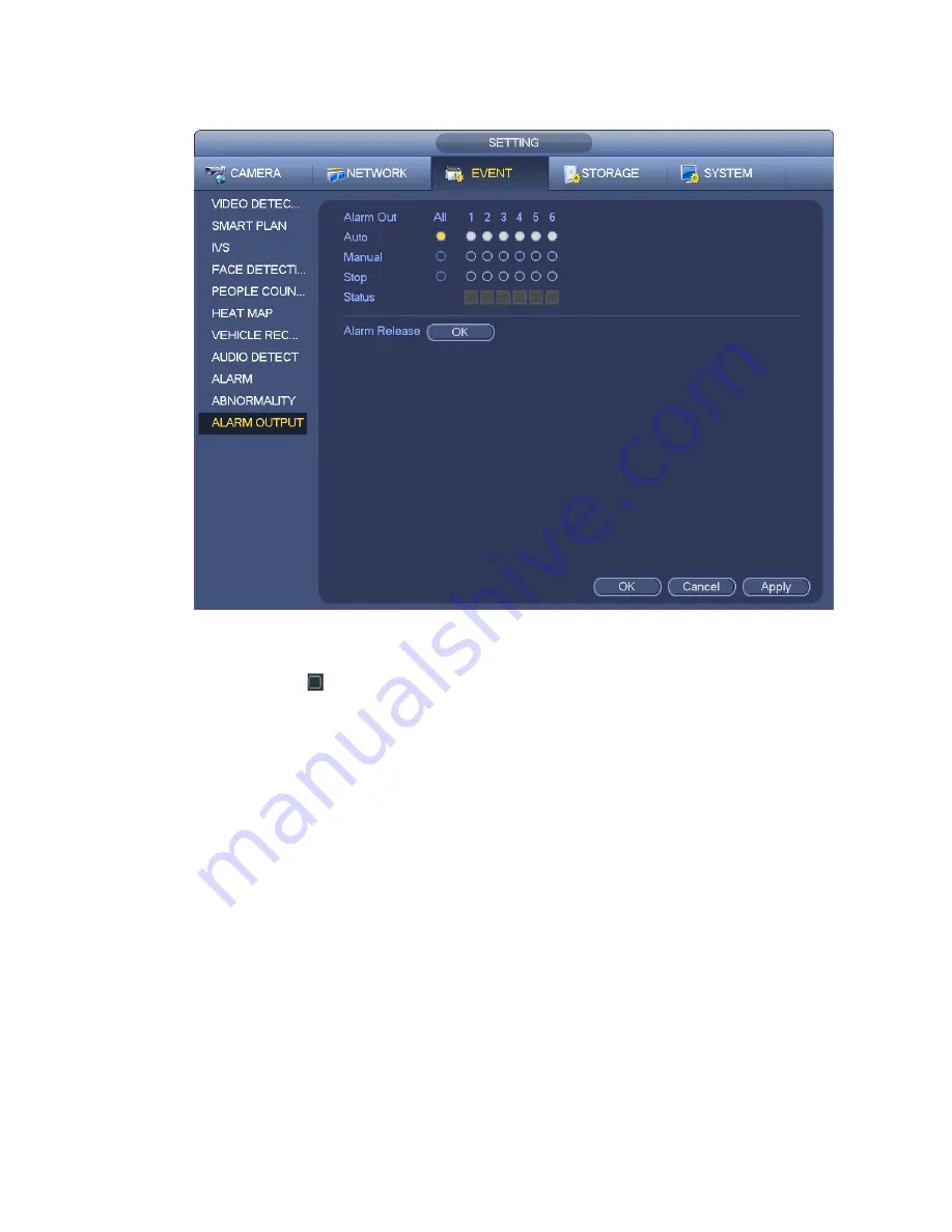
Here is for you to set proper alarm output (Auto/manual/stop).
Click OK button of the alarm reset, you can clear all alarm output status.
Figure 4-160
Please highlight icon
to select the corresponding alarm output.
After all the setups please click OK button.
4.8 Network
4.8.1
Network Settings
4.8.1.1 TCP/IP
The single network adapter interface is shown as in Figure 4-161 and the dual network adapters interface
is shown as in Figure 4-162.
Network Mode : Includes multiple access, fault tolerance, and load balancing
Multiple-address mode: eth0 and eth1 operate separately. You can use the services such as
HTTP, RTP service via etho0 or the eth1. Usually you need to set one default card (default setup
is etho) to request the auto network service form the device-end such as DHCP, email, FTP and
etc. In multiple-address mode, system network status is shown as offline once one card is
offline.
Network fault-tolerance: In this mode, device uses bond0 to communicate with the external
devices. You can focus on one host IP address. At the same time, you need to set one master
card. Usually there is only one running card (master card).System can enable alternat e card
when the master card is malfunction. The system is shown as offline once these two cards are
both offline. Please note these two cards shall be in the same LAN.
Содержание NVR-ELE4ME-WS
Страница 1: ...1080p Resolution 1yr Warranty Motion Activated Recording PTZ Control View From Anywhere NVR ELE4ME WS...
Страница 33: ...163 Figure 3 3 3 5 4 Compact 1U Series Please refer to Figure 3 4 for connection sample...
Страница 34: ...164 Figure 3 4 3 5 5 Compact 1U Wireless Series Please refer to Figure 3 5 for connection sample...
Страница 43: ...173 Figure 3 16 3 5 17 Professional 1 5U Series Please refer to Figure 3 17 for connection sample...
Страница 45: ...175 Figure 3 18 3 5 19 Professional 2U Series Please refer to Figure 3 19 for connection sample...
Страница 47: ...177 Figure 3 20 3 5 21 Professional 2U with RAID series Please refer to Figure 3 21 for connection sample...
Страница 48: ...178 Figure 3 21 3 5 22 Professional 3U Series Please refer to Figure 3 22 for connection sample...
Страница 50: ...180 Figure 3 23 3 5 24 Beneficio Vertical 1U Series Please refer to Figure 3 24 for connection sample...
Страница 51: ...181 Figure 3 24...
Страница 63: ...193 Figure 4 14 Figure 4 15 Step 2 Set network camera login password WARNING...
Страница 71: ...201 Figure 4 24 Step 2 Click device display edit interface See Figure 4 25...
Страница 148: ...278 Figure 4 114 Figure 4 115...
Страница 159: ...289 Figure 4 126 Figure 4 127...
Страница 161: ...291 Figure 4 129 Click draw button to draw the zone See Figure 4 130...
Страница 165: ...295 Figure 4 133 Click Draw button to draw a zone See Figure 4 134 Figure 4 134...
Страница 170: ...300 Figure 4 139 Click draw button to draw the zone See Figure 4 140...
Страница 183: ...313 Figure 4 151 Figure 4 152...
Страница 184: ...314 Figure 4 153 Figure 4 154...
Страница 214: ...344 Figure 4 189 In Figure 4 189 click one HDD item the S M A R T interface is shown as in Figure 4 190 Figure 4 190...
Страница 250: ...380 Figure 4 236...
Страница 294: ...424 Figure 5 60 Figure 5 61...
Страница 295: ...425 Figure 5 62 Figure 5 63...
Страница 319: ...449 Figure 5 97 Figure 5 98...
Страница 322: ...452 Figure 5 101 Figure 5 102...


