Page 44
7.5 12 AND 24 INCH BRAKES
Brakes are component tools designed to bend and form mild steel. They are shipped standard with dies
to accommodate material up to 1/4 of an inch (6mm) thickness. The selector switch must be in the
SHEAR position to operate these tools.
7.5A BRAKE INSTALLATION
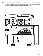
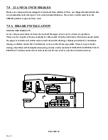
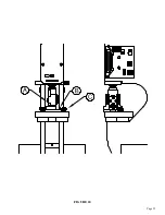
SEE FIGURE 18 BELOW.
Grease the pressure block between the tool and the upper arm every two hours of operation.
There are two lengths of brakes available for this model: 12 inch and 24 inch. The brakes mount under
the upper arm in the tool station and are held down with the finger clamps provided. For maximum
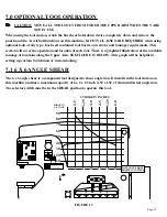
tonnage available, mount the 12 inch brake as close to the frame as possible. There is a press brake
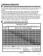
tonnage chart that will be helpful when using a brake on this machine ON THE FOLLOWING PAGE,
FIGURE 19. On this model, the 12 inch brake has 50 tons of force and the 24 inch has 40 tons.
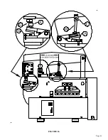
FIGURE 18
Содержание 9012-24M
Страница 10: ...Page 9 FIGURE 1 ...
Страница 12: ...Page 11 FIGURE 2 ...
Страница 16: ...Page 15 FIGURE 4A ...
Страница 17: ...Page 16 FIGURE 4B ...
Страница 18: ...Page 17 FIGURE 4C ...
Страница 22: ...Page 21 FIGURE 6 ...
Страница 24: ...Page 23 FIGURE 7 ...
Страница 35: ...Page 34 THIS PAGE LEFT BLANK INTENTIONALLY ...
Страница 40: ...Page 39 FIGURE 15 ...
Страница 42: ...Page 41 FIGURE 16 ...
Страница 48: ...Page 47 FIGURE 20 ...
Страница 54: ...Page 53 FIGURE 24 ...
Страница 56: ...Page 55 FIGURE 25 ...
Страница 62: ...Page 61 FIGURE 27 ...
Страница 66: ...Page 65 FIGURE 29 ...
Страница 68: ...Page 67 FIGURE 30 ...
Страница 74: ...Page 73 FIGURE 32 ...
Страница 78: ...Page 77 FIGURE 34 ...
Страница 80: ...Page 79 FIGURE 35 ...
Страница 82: ...Page 81 FIGURE 36 ...
Страница 84: ...Page 83 FIGURE 37 ...
Страница 86: ...Page 85 FIGURE 38 ...
Страница 90: ...Page 89 FIGURE 41 ...
Страница 92: ...Page 91 FIGURE 42 ...
Страница 93: ...Page 92 FIGURE 43 ...
Страница 96: ...Page 95 THIS PAGE LEFT BLANK INTENTIONALLY ...
Страница 98: ...Page 97 FIGURE 46 ...
Страница 100: ...Page 99 FIGURE 47 ...

