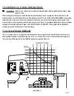
background image

Page 39

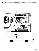
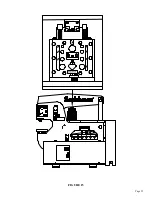
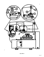
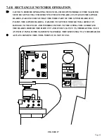
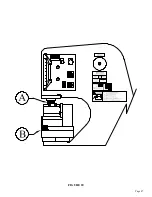
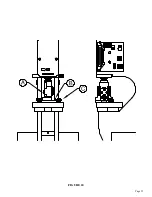
FIGURE 15

Содержание 9012-24M

Страница 1: ...htness Punch half holes punch or shear unknown materials side load DO NOT REMOVE THIS SIGN FROM THIS MACHINE REV 0310 FOR MORE INFORMATION CONTACT SCOTCHMAN INDUSTRIES INC 1 800 843 8844 003100 proper instructions and without reading and understanding the hold downs in place members Check alignment and tightness daily press brakes AT LUBRICATE BEFORE OPERATING 19103 0481 LUBRICATE BEFORE OPERATING...

Страница 2: ...www scotchman com MODEL 9012 24M IRONWORKER SCOTCHMAN INDS 180 E HWY 14 PO BOX 850 PHILIP SD 57567 PHONE 1 800 843 8844 PRINTED SEPTEMBER 2021 ...

Страница 3: ...ons 13 4 4 Electrical Requirements 14 4 5 Machine Start Up 14 4 6 Machine Stroke Inspection Adjustment 18 5 0 MAINTENANCE 20 23 5 1 Lubrication 20 5 2 Routine Lubrication 20 5 3 Scheduled Maintenance 22 6 0 MACHINE OPERATION 24 34 6 1 Punch Operation 24 6 1B Stripper Adjustment 28 6 2 Bar Shear Operation 29 6 2A Shear Arm Adjustment 30 6 2B Shear Blade Adjustment 32 7 0 OPTIONAL TOOL OPERATION 35 ...

Страница 4: ...3 Die Inserts 56 7 11B Offset Die Holder 56 7 11C 6 x 6 Die Holder 56 7 11D 45 Punch Retaining Nut 56 7 11E Heavy Duty Split Ring Retaining Nut 56 7 12 Optional Gauging Equipment 58 7 12A 48 Inch Deluxe Back Gauge 58 7 13 Urethane Stripper 59 7 14 Weld Coupon Bender Tool 64 7 15 Multi Shear Tool 66 8 0 TROUBLE SHOOTING GUIDE 68 71 8 1 Electrical Trouble Shooting Motor 68 8 2 Limit Switch Inspectio...

Страница 5: ...r Assembly 76 9 4 Urethane Stripper 78 9 5 Upper Arm Assembly 80 9 6 Stroke Control Assembly 82 9 7 Hold Down Assembly 84 9 8 Cylinder Assembly 86 9 9 Connecting Link Assembly 87 9 10 Power Unit Serial 20661 Up 88 9 11 Electrical Unit 90 9 12 Standard Die Holder w Inserts 93 9 13 Punch Retaining Nuts 94 10 0 SUPPLEMENT FOR OLDER MODELS 95 99 ...

Страница 6: ... stroke stop jog or reverse gives the Scotchman 9012 24M Ironworker a tremendous advantage over mechanical ironworkers There is no chance of the Scotchman being accidentally tripped The hydraulic system operates at a maximum pressure of 2 650 PSI 183 BAR and is protected from overload by a pilot operated relief valve The Scotchman 9012 24M Ironworker lends itself to a variety of special purpose to...

Страница 7: ... disconnect and lock out the power when performing maintenance work or setting up any tooling on the machine Follow the procedures outlined in the operator s manual for setting up changing or aligning any tooling on this machine 7 Never operate this machine with dull or damaged tooling Replace worn punches dies and blades promptly 8 Practice good housekeeping Keep the area around the machine clear...

Страница 8: ... modified in any way or subjected to abusive and abnormal use inadequate maintenance and lubrication or subjected to use beyond the seller s recommended capacities and specifications In no event shall seller be liable for labor cost expended on such goods or consequential damages The seller shall not be liable to purchaser or any other person for loss or damage directly or indirectly arising from ...

Страница 9: ...03120 DANGER VOLTAGE LABEL E 2 003140 FINGER BEYOND TOOL SHEAR F 1 019107 U S FLAG DECAL G 1 003195 3 X 3 X 1 4 MAX STICKER H 1 010117 27 SCOTCHMAN DECAL I 1 019139 90T CAPACITY DECAL J 4 019103 LUBRICATE DECAL 4 K 9 019105 GREASE POINT DECAL 7 L 1 003175 CAUTION CONTAMINATION Not shown M 1 019102 RESERVOIR CAPACITY Not shown O 1 003540 90T DECAL PACKAGE ...

Страница 10: ...Page 9 FIGURE 1 ...

Страница 11: ...4 1 PHYSICAL DIMENSIONS INCHES CM A Floor to Punch Ram 43 3 16 109 7 B Floor to Top of Die Holder 41 104 1 C Floor to Punch Bolster 36 3 8 92 4 D Floor to Bottom Rail 3 7 6 E Floor to Bar Shear 29 13 16 75 7 F Floor to Tool Table 45 3 16 114 8 G Height 71 1 4 181 H Length 76 193 I Punch Stroke 2 1 4 5 7 J Width 30 7 8 78 3 K Weight 4 000 LBS 1 814 KG ...

Страница 12: ...Page 11 FIGURE 2 ...

Страница 13: ... 1 818 Kg Check the capacity of the lifting equipment before attempting to move the machine THIS MACHINE IS TOP HEAVY AND SHOULD BE MOVED WITH CARE AND ON FLAT SURFACES ONLY This is the quickest and safest means of moving the machine The forks of the lift should be spread so that they fit inside the lifting channels provided FIGURE 3 ...

Страница 14: ...tches B Pump and motor assembly C Hydraulic hoses and fittings D Starter box and control box E Electrical connections F Control valve The reservoir is full of oil The recommended oil is a lightweight non foaming anti wear hydraulic oil such as Mobil DTE 25 with a minimum ISO cleanliness code of 20 18 15 or equivalent The reservoir holds 13 5 U S gallons 51 liters 4 3 PHYSICAL INSPECTIONS CAUTION D...

Страница 15: ...Before starting this machine take time to thoroughly review the safety CD and the operator s manual This machine is equipped with a lock out disconnect switch We strongly urge you to follow OSHA directive CFR 1910 147 effective 09 01 90 regarding lock out tag out procedures Before powering the machine be sure that all packing materials and tools have been removed from the machine and that the work...

Страница 16: ...Page 15 FIGURE 4A ...

Страница 17: ...Page 16 FIGURE 4B ...

Страница 18: ...Page 17 FIGURE 4C ...

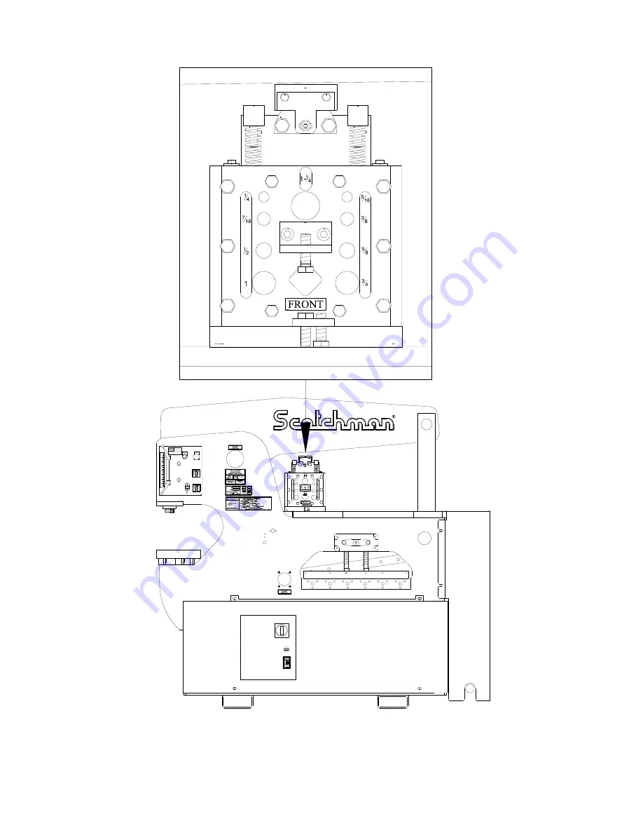
Страница 19: ...Measure the distance from the top of the punch bolster to the bottom of the punch ram The distance should be 9 1 32 inches 229mm Turn the selector switch to the PUNCH position and measure the distance The distance should be 6 25 32 inches 172mm These dimensions are are or 1 16 of an inch 3mm IF THE STROKE IS OUT OF THESE LIMITS THEN USE THE FOLLOWING PROCEDURE 1 Loosen the two mounting plate screw...

Страница 20: ...80 70 60 50 40 30 20 10 10 90 80 70 60 50 40 30 20 3 2 1 3 2 1 0 004085 DO NOT EXCEED 3 X 3 X 1 4 WHEN MITERING 0502 003195 P N 16247 65 90 120 AS FI60 85 BK 90 120 RS 201110 M6x12 201110 M6x12 JOG START STOP RUN JOG START SHEAR PUNCH PROBE 004085 7711 Sales 7710 Assy 080061 080061 9 1 32 229mm UP 6 25 32 172mm DOWN ...

Страница 21: ...uirt can or a spray applicator 5 1 LUBRICATION Grease the main pins A B and the punch ram C daily SEE FIGURE 6 ON THE FOLLOWING PAGE Grease all other fittings twice per week A multi purpose Molybdenum Disulfide Dow Corning BR 2 or equivalent high pressure bearing grease is recommended Check the oil level in the reservoir at least once a month It should be 1 1 2 inches below the top of the reservoi...

Страница 22: ...Page 21 FIGURE 6 ...

Страница 23: ...punch ram and the bushing Care should be taken when removing these parts THEY ARE HEAVY 6 Clean all grease and dirt off both parts and check the clearance between the outside diameter of the punch ram and the inside diameter of the punch ram bushing If the clearance between the two parts is five thousandths 005 of an inch or more replace both parts Reassemble parts in reverse order B Check the con...

Страница 24: ...Page 23 FIGURE 7 ...

Страница 25: ...TION 6 1 PUNCH OPERATION WHEN USING A URETHANE STRIPPER SEE SECTION 7 13 FOR INSTRUCTIONS ALWAYS WEAR SAFETY GLASSES THE FIRST AND MOST IMPORTANT PROCEDURE IS THE PROPER METHOD OF CHANGING AND ALIGNING PUNCHES AND DIES FIGURE 8 ...

Страница 26: ... SPECIAL INSTRUCTIONS IN SECTION 7 9B BEFORE CONTINUING 6 Place the disconnect switch in the ON position and the selector switch in the START position Power the machine by pressing the green START button 7 Check to make sure that there are no objects such as tools on or under any of the moving parts 8 Place the selector switch in the SHEAR position and allow the ram to extend 9 Turn the machine s ...

Страница 27: ...die Turn off the machine Check and tighten the punch retaining nut the bolt holding the die the two set screws holding the die insert and the two bolts holding the die holder Check for equal clearance between the punch and die Place the selector switch in the START position and power the machine Place the selector switch in the SHEAR position Use the foot switch to jog the machine several times to...

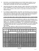
Страница 28: ...E HOLES DO NOT PUNCH PARTIAL HOLES The side thrust encountered in punching a partial hole can force the punch over against the die and result in punch or die breakage This may result in serious bodily injury F MAINTAIN SUFFICIENT MATERIAL BETWEEN THE PUNCHED HOLE AND THE EDGE OF THE WORKPIECE The edge of the punch should be clear of the edge of the workpiece by a distance equal to the thickness of...

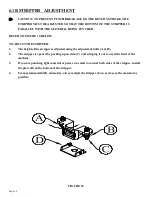
Страница 29: ...RIPPER 1 The height of the stripper is adjusted using the adjustment bolts A B 2 The stripper is opened by pushing up on item C and swinging it out toward the front of the machine 3 If you are punching light material or pieces too small to contact both sides of the stripper install the plate D on the bottom of the stripper 4 For maximum visibility and safety always adjust the stripper down as clos...

Страница 30: ...e NEVER put any part of your body between the hold down and the material to be sheared A clearance of 1 8 inch 3mm between the hold down and material to be sheared is acceptable The maximum tonnage available on the bar shear is to the left or closest to the pivot point For applications that do not require the maximum tonnage move the material to the right for minimal distortion on the drop piece D...

Страница 31: ...metrical and can be rotated to expose four 4 cutting edges For recommended clearances SEE FIGURE 12 ON PAGE 33 B ALL CUTS SHOULD BE MADE AS FAR FROM THE ARM PIVOT AS POWER WILL PERMIT The Shear Blades should contact the workpiece as flat as possible to reduce to a minimum the amount of curl on the cut off piece More shearing force is obtained as the operator moves the workpiece toward the left The...

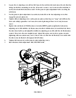
Страница 32: ...arm solidly against the rear frame Excessive tightening of these screws only increases wear 5 Replace the rub block I With the shear arm in the DOWN position tighten the bottom two adjusting screws H until the rub block comes in contact with the shear arm rub block J Raise the arm about half way and adjust the middle two adjusting screws H until the rub block makes contact Then raise the arm compl...

Страница 33: ...ust the lower blade to the top blade with the upper adjusting screws D about 1 8 of a turn past resistance 10 Tighten the bolts E to 1 4 a turn past resistance 11 Adjust the lower adjusting screws D up to the blade and then tighten all of the bolts starting with the blade bolts E and then the adjusting screws D 12 CAUTION THE BLADES MUST BE ADJUSTED PARALLEL TO EACH OTHER vertically or with the cu...

Страница 34: ...h final tighten blade bolts then set screws MAKE SURE BLADES HAVE PROPER CLEARANCE AND ARE PARALLEL LOWER BLADE MAY HAVE A SLIGHT CANT AS SHOWN CHANGING BAR SHEAR BLADES QUICK GUIDE TO UPPER LO W ER 2 CANT 080174 Grease Bolt 201610 243101 210014 M12 Jam 218120 210014 M12 Jam 218120 210014 M12 Jam 218120 210014 M12 Jam 218120 510 09 510 09 218120 214014 214014 214014 214014 214014 214014 221426 M16...

Страница 35: ...Page 34 THIS PAGE LEFT BLANK INTENTIONALLY ...

Страница 36: ... service or adjust machine without operator s manual and safety film Service machine with electrical power connected Operate any station without the respective strippers or Operate machine with protective guards removed Place any part of your body under blade punch or moving Operate punch station without checking the punch to die alignment and tightness Punch half holes punch or shear unknown mate...

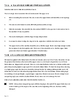
Страница 37: ...6 X 6 ANGLE SHEAR OPERATION Oil must be applied to the blades before the first cut is made and every 10 to 15 cuts thereafter Grease the pressure block between the tool and the upper arm every two hours of operation A set of lower blade shims are shipped with each unit These are to be installed between the lower blades and the side plate when shearing lighter angle up to 5 16 of an inch 8mm thick ...

Страница 38: ...ge 37 CAUTION IF THE ANGLE SHEAR SHOULD JAM FOR ANY REASON DO NOT ATTEMPT TO FREE IT BY HAND USE A PRY BAR OR SIMILAR DEVICE REPLACE THE BLADES OR INSTALL SHIMS DEPENDING ON WHAT CAUSED THE JAM FIGURE 14 ...

Страница 39: ... practical location under the upper arm CAUTION TO PREVENT DAMAGE TO THE TOOL THE STROKE OF THE MACHINE MUST BE SET WHEN USING THE ROD SHEAR Set the upstroke of the machine so that the workpiece easily slides through the tool Set the down stroke so that the cut can be made with a minimum amount of stroke Failure to set the stroke of the machine will damage the tool 7 2B ROD SHEAR OPERATION Oil the...

Страница 40: ...Page 39 FIGURE 15 ...

Страница 41: ...ch 1 5mm To install the notcher under the upper arm the tool should be mounted as close to the frame as possible and anchored with the bolts and thick washers A provided The pusher B and beam block C should be installed according to the dimensions IN FIGURE 16 To mount the notcher in the punch station first remove the die holder stripper and punch Mount the short punch pusher G with the standard j...

Страница 42: ...Page 41 FIGURE 16 ...

Страница 43: ... the upper blade with the rear of the lower blades There should be a clearance of approximately 005 of an inch 12mm on each side 7 Tighten the upper blade bolts To check blade alignment raise and lower the upper casting several times by hand After alignment tighten the back up set screws to make sure that the upper blade does not move 7 4 RECTANGLE NOTCHER The Rectangle Notcher is a component tool...

Страница 44: ... FAR ENOUGH SO THAT THE WIDE PART OF THE UPPER BLADE JUST PASSES THE LOWER BLADES FAILURE TO SET THE STROKE WILL RESULT IN DAMAGE TO THE TOOL AND POSSIBLE INJURY TO THE OPERATOR LUBRICATE THE BLADES BEFORE THE FIRST CUT AND EVERY 10 15 CUTS THEREAFTER 3 8 OF AN INCH 9 5MM IS THE MAXIMUM MATERIAL THICKNESS THAT CAN BE SHEARED ALWAYS REMOVE THIS TOOL WHEN IT IS NOT IN USE FIGURE 17 ...

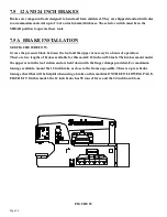
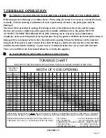
Страница 45: ... the tool and the upper arm every two hours of operation There are two lengths of brakes available for this model 12 inch and 24 inch The brakes mount under the upper arm in the tool station and are held down with the finger clamps provided For maximum tonnage available mount the 12 inch brake as close to the frame as possible There is a press brake tonnage chart that will be helpful when using a ...

Страница 46: ...TALS AS COMPARED TO 65 000 P S I TENSILE MILD STEEL ON CHART SOFT BRASS 50 OF PRESSURE LISTED SOFT ALUMINUM 50 OF PRESSURE LISTED ALUMINUM ALLOYS HEAT TREATED SAME AS STEEL STAINLESS STEEL 50 MORE THAN STEEL CHROME MOLYBDENUM 100 MORE THAN STEEL FIGURE 19 Hold short pieces with tongs or a similar device When using the brake it is necessary to load the brake centrally Visual centering is sufficient...

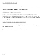
Страница 47: ...t be in the PUNCH position to operate this tool The die holder punch retaining nut and the stripper must be removed to install this tool Mount the tool so that it lines up directly under the punch ram A and anchor it to the punch bed with the clamps B provided 7 6B ANGLE IRON BRAKE OPERATION The down stroke of the machine must be set to prevent damage to the tool Grease the brake guides every two ...

Страница 48: ...Page 47 FIGURE 20 ...

Страница 49: ...E OF CHANNEL BEING SHEARED Improper adjustment of the vertical blades will result in damage to the channel shear It is necessary to reset the stationary side blades for each size of channel to keep the channel centered in the unit ONE METHOD OF ACCOMPLISHING THIS ADJUSTMENT IS AS FOLLOWS Place a piece of channel the size to be sheared in the tool Remove the lifting springs and lower the upper blad...

Страница 50: ... the foot switch back the movable blades off by 1 2 turn of the locking handle Make sure that the slug drops from the chute after each stroke All of the bottom and vertical blades are symmetrical and can be turned to present four 4 cutting edges Clearance between the upper and lower blades is changed by the addition or removal of shims A clearance of twenty thousandths of an inch 5mm is recommende...

Страница 51: ...to the tool table with the M 12 bolt G provided 3 Both the 6 x 6 Angle Shear and the Pipe Notcher can be used on the tool table at the same time CAUTION With the tool mounted in either station it is necessary to set the down stroke of the machine to prevent damage to the tool The upper die should not pass the lower die by more than1 32 of an inch 7mm 7 8B PIPE NOTCHER OPERATION To achieve the best...

Страница 52: ...S Two inch 2 Schedule 80 is the maximum thickness that can be cut Lighter weight tubing may be cut but will probably require different dies for best cutting results Separate dies are required for each size of pipe or tubing being notched FIGURE 23 ...

Страница 53: ...FORE OPERATION OF THE TOOL FAILURE TO SET THE DOWNSTROKE OF THE MACHINE WILL RESULT IN DAMAGE TO THE TOOL 1 Set the down stroke of the machine so that the upper die clears the lower die by twice the wall thickness of the tube plus 1 32 of an inch 8mm 2 Adjust the tube stop A just low enough to contact the upper edge of the tube 3 Adjust the rest stop B so that it is approximately half of the tube ...

Страница 54: ...Page 53 FIGURE 24 ...

Страница 55: ...ter 3 Anchor the tool with the finger clamps C provided 4 Set the upstroke of the machine so that the size of tube you want to shear will feed through the tool Make sure that the upstroke is set so that there is spring tension on the pressure block at all times 5 Set the down stroke so that the upper blade passes the lower blade by approximately 1 8 3mm 7 10A SQUARE TUBE SHEAR INSTALLATION 1 The s...

Страница 56: ...Page 55 FIGURE 25 ...

Страница 57: ...ffset die holder is designed to be used in conjunction with an offset stripper The standard stripper will not work with the offset die holder Always follow the preferred method of aligning punches and dies SEE SECTION 6 1 The 6 x 6 die holder is installed in place of the standard die holder The 6 x 6 die holder requires four mounting bolts that are shipped with the tool Capacities for oversize pun...

Страница 58: ...ank diameter E This retaining nut requires a pin wrench F which should be ordered when ordering the nut Follow the instructions in SECTION 6 1 for proper punch and die alignment To use the heavy duty split ring retaining nut remove the six socket head cap screws D Slide the retaining ring C over the punch shank Place the split ring B into the groove on the punch Place the ring nut A on the punch a...

Страница 59: ...mounts on the drop off side of the machine and will reach all three stations from one point It is designed to be used as a length stop in the shear punch and tooling stations It is available with a scale a digital readout or an electrically controlled stop For parts identification SEE THE TOOLING PARTS MANUAL ...

Страница 60: ... without causing some deformation Contact your dealer or Scotchman for advice Combining this unit with a linear feed repetitive stop system for punching a series of holes in flat bar will significantly increase productivity Because of the action of this type of unit particular attention must be paid when setting the stroke length The stripper unit moves in conjunction with the punch and extra care...

Страница 61: ...m plate item 11 Loosen and remove both nyloc nuts 6 When loosening the nyloc nuts 6 if one or both tie rods become loose remove the loose tie rod s from the base plate and remove the nut s from the tie rod s Re tighten the tie rod s into the base plate and lock in place using a thread locking solution such as Nutloc Remove items 1 and 7 top plate and spring spacers Remove item 3 urethane springs R...

Страница 62: ...Page 61 FIGURE 27 ...

Страница 63: ... in the die insert Tighten the bolt firmly with a wrench 11 Insert the punch into the punch retaining nut Make sure that it seats properly Place the punch retaining nut assembly on the die insert J with the punch inserted in the die NOTE IF YOU ARE USING PUNCHES THAT REQUIRE A KEY INSERT THE KEY IN THE PUNCH AT THIS POINT 12 Place the disconnect switch in the ON position and the selector switch in...

Страница 64: ...nger tighten the retaining nuts I 23 Power the machine and jog the ram down until the urethane stripper contacts the top of the die die holder Continue to jog the ram down compressing the urethane springs until the retaining nuts I can be tightened down to the shoulder on the stud 24 Install the stripper guard H on the front of the stripper CAUTION REMEMBER THAT THE MAXIMUM CAPACITY OF THIS STRIPP...

Страница 65: ...oke 7 14A WELD COUPON BENDER TOOL INSTALLATION NOTE THE DOWN STROKE MUST BE SET PROPERLY WITH THIS TOOL 1 Grease the rocker cap B between the upper arm and the tool and again after every two hours of use Grease the ram using the two grease zerks on the side 2 Lightly grease the rollers using the two grease zerks on the front of the weld tester Make sure that the rollers still turn easily too much ...

Страница 66: ...Page 65 FIGURE 29 ...

Страница 67: ...ol is squarely under the beam tighten the finger clamps B to hold the tool in place 5 Set the upstroke of the machine so that the size of material that you want to shear will feed through the tool 6 Make sure that the upstroke is set so that there is spring tension on the pressure block at all times 7 Set the down stroke of the machine so that the moving blade travels only far enough to shear the ...

Страница 68: ...Page 67 FIGURE 30 ...

Страница 69: ...not move 3 Check the stroke control adjustment and make sure that only one limit switch is in contact with the contact blocks If both limit switches are in contact with the contact blocks the machine will not move Loosen the stroke control handles and move the contact blocks Try the machine again 4 Check the fuses in the control box There are two fuses in line on the primary side Remove the fuses ...

Страница 70: ...ure that the power to the machine is off and locked out The wires must be disconnected from the pedal and the terminal blocks 8 2 LIMIT SWITCH INSPECTION PROCEDURE The limit switches are sealed units and cannot be taken apart The plunger can be manually checked It should move freely in and out The switches can also be tested with an Ohm meter The wires must be disconnected from the terminal blocks...

Страница 71: ...ustable by adjusting the relief valve on the control valve manifold If the pressure cannot be increased call your local dealer or the factory 8 4 HYDRAULICS Use the following steps to replace the seals in the hydraulic cylinder SEE FIGURE 31 ON THE FOLLOWING PAGE 1 With the selector switch in the SHEAR position and the arms up turn the machine s power off at the disconnect switch and lock it 2 Blo...

Страница 72: ...ube with a brass or plastic hammer 13 Re thread the cylinder head into the tube 14 Reconnect the hoses to the cylinder 15 Use care removing the blocking device A from under the arms Since the cylinder does not contain oil it may drop some when the blocks are removed 16 Cycle the machine several times to purge the air out of the hydraulic system FIGURE 31 ...

Страница 73: ... Shear Table G 010182 Main Pin Bushing H 030556 Shear Arm Pin I 080174 Grease Bolt J 012121 Pressure Plate K 037273 Brass Plate 2 Required L 218120 M 12 Set Screw M 214014 M 12 Washer N 212014 M 12 Lock Washer O 218120 M 12 Set Screw P 205422 M 12 HHCS Q 221322 M 12 SHCS R 080428 Shear Slug Chute S 030660 Tooling Slug Chute T 201220 M 10 HHCS U 218112 M 12 Set Screw V 006015 Shear Arm Rub Plate W ...

Страница 74: ...Page 73 FIGURE 32 ...

Страница 75: ...7 Lower Punch Pin O 016620 2 Snap Ring P 016625 2 1 2 Snap Ring Q 032074 Upper Punch Pin Bushing Inc P U R 210014 M 12 Hex Nut S T 030619 Punch Link Set Includes CC DD U 243101 Grease Zerk V 201440 M 12 Hex Bolt W M 010236 Punch Ram Bushing X 030657 Punch Shroud Z 224205 M 10 x 16 WLCS AA 077145 Hardened Pin BB 004123 1 4 Key CC 080192 2 1 2 Brass Spacer DD 015131 2 Brass Spacers EE 012078 3 Punch...

Страница 76: ...0 192 080 192 015 131 015 131 243101 243101 201440 M12x100 Q 210014 M12 Jam BB GG U P N 010236 Kit 012076 030 645 243101 Includes M W EE FF and GG HH 221120 M8 x 25 221120 M8 x 25 221120 M8 x 25 221120 M8 x 25 221120 M8 x 25 221120 M8 x 25 221120 M8 x 25 221120 M8 x 25 221420 M16 x50 2214 20 M16x50 221420 M16x50 221420 M16x50 221420 M16 x50 221315 M12x40 221315 M12x40 221315 M12x40 221315 M12x40 0...

Страница 77: ... 007240 Spring Retainer E 007241 Spring F 007236 Adjustment Screw Right G 007239 Spring Rod H 220014 M 6 x 10 BHCS I 007268 Sight Glass 5 x 2 5 16 J 001541 Ball Spring Set Screw K 230007 M 6 x 16 FSHCS L 007244 Stripper Retainer N 007253 Stripper Plate Includes J O O 110014 1 2 x 13 Jam Nut P 007233 Complete Stripper Includes all items on this page ...

Страница 78: ...Page 77 FIGURE 34 ...

Страница 79: ...ring Post 5 025456 Spring Spacer 6 025453 Post Nut 7 025441 Top Plate 8 073691 Knob 9 221326 M 12 x 65 SHCS 10 218023 M 6 x 12 SS 11 025447 Stripper Plate 12 026039 Die Holder 026030 Complete Unit 13A 026042 Bolster Ser 21601 Up 13B 026043 Bolster Ser 21600 Prior 026060 Retro Fit Kit Ser 21601 Up 026065 Retro Fit Kit Ser 21600 Prior ...

Страница 80: ...Page 79 FIGURE 35 ...

Страница 81: ...PER ARM ASSEMBLY ITEM PART DESCRIPTION A 030560 Upper Arm Includes A B D F B 006172 Bushing C 080174 Grease Bolt D 012070 Upper Arm Bushing E 035666 Upper Arm Pin F 032074 Punch Pin Bushing G 212016 M 16 Lock Washer ...

Страница 82: ...Page 81 FIGURE 36 ...

Страница 83: ... Start Legend 12 011874 Contact Block 13 011501 Punch Start Shear 14 011868 Three Position Switch 15 158101 Hole Plug 16 080061 Handles 17 004087 Pointer 18 004086 Limit Switch Mount 19 562113 Limit Switch 20 073450 M 4 x16 SHCS 21 030407 Metering Boss 22 011502 Jog Run Probe Legend 23 011868 Three Position Switch 24 003200 Jog Legend 25 011884 Jog Button Assembly 26 011874 Contact Block 27 011873...

Страница 84: ...Page 83 FIGURE 37 ...

Страница 85: ...05 Warning Label H 080348 Gear Center I 080349 Gear Right J 080338 Wheel Shaft K 080344 Base L 201110 M 6 x 12 HHCS M 141415 1 4 x 1 3 4 Roll Pin N 017342 Hold Down Crank Includes 2 each O P Q O 210014 M 12 Jam Nut P 017347 Handle Q 221335 M 12 x 80 SHCS R 221120 M 8 x 25 SHCS S 080339 Wheel Washer T 221320 M 12 x 50 SHCS U 212014 M 12 Lock Washer 017341 Complete Hold Down ...

Страница 86: ...Page 85 FIGURE 38 ...

Страница 87: ...r Includes B D 030595 Cylinder Anchor Pin E 016620 2 Snap Ring F 030233 Cylinder Shroud G 224205 M 10 WLCS H 030631 Rear Shroud Ser 20600M Prior H1 080423 Rear Shroud Ser 20601M Up I 030637 Front Shroud Ser 20600M Prior I1 080422 Front Shroud Ser 20601M Up J 030610 Cylinder Seal Kit Not Pictured FIGURE 39 ...

Страница 88: ...Page 87 9 9 CONNECTING LINK ASSEMBLY ITEM PART DESCRIPTION A 030570 Connecting Link B 006190 Connecting Link Pins C 016620 2 Snap Ring D 243101 M 6 Grease Zerk FIGURE 40 ...

Страница 89: ...ting H 006830 Suction Hose I Fitting J Motor Must specify K 007340 Pump L 006960 Motor Pads M 003952 Fitting N 006835 Pressure Hose O Fitting P Manifold Mounts Q 006870 Manifold Q1 006865 Relief Cartridge R 552180 Parker Valve R1 552181 Parker Coil For 552180 R2 552135 Sales Valve Assembly S Fitting T Reservoir U 158050 Magnetic Plug V 003780 Cylinder Hose Bottom W 003780 Cylinder Top X 006850 Inl...

Страница 90: ...Page 89 FIGURE 41 ...

Страница 91: ...Switch Knob G See note Contactor DIL M G1 See note 011976 Contactor DIL 230 Volt 1PH 3PH G2 See note 011975 Contactor DIL 460 575 Volt H See note 011999 Overload 230 Volt 3ph 1ph ZB32 24 See note 011998 Overload 460 Volt ZB32 10 See note 011998 Overload 575 Volt ZB 32 10 I 011873 Start Switch Lamp J 060083 Aux Contact NOTE IF WE ARE OUT OF STOCK WITH THE DIL OLD STYLE CONTACTOR OR OVERLOAD BOTH TH...

Страница 92: ...Page 91 FIGURE 42 ...

Страница 93: ...Page 92 FIGURE 43 ...

Страница 94: ...T DESCRIPTION A 006013 Cast Die Holder B 006302 3 Die Insert 76mm C 006252 2 1 2 Die Insert 63mm D 006202 2 Die Insert 50mm E 218058 M 10 Set Screw F 201625 M 16 HHCS G 113017 Reid Washer H 077145 Pin I 219060 M 10 x 50 SS J 204220 M 10 x 30 HHCS FIGURE 44 ...

Страница 95: ...ng Nut B 026502 Split Ring C 026503 Retaining Ring D 221212 M 10 SHCS E 026504 M 8 Brass Set Screw F 016095 40 Punch Retaining Nut G 016096 45 Punch Retaining Nut H 018507 Wrench For A I 019098 Wrench For F G 026500 Complete Heavy Duty Nut Includes A B C D E FIGURE 45 ...

Страница 96: ...Page 95 THIS PAGE LEFT BLANK INTENTIONALLY ...

Страница 97: ...30555 Shear Arm Pin I 080174 Grease Bolt J 012121 Pressure Plate K 037273 Brass Plate 2 Required L 218120 M 12 Set Screw M 210014 M 12 Jam Nut N 230207 M 10 FSHCS O 221417 M 16 SHCS P 205425 M 12 HHCS Q 221322 M 12 SHCS R 080310 Shear Slug Chute S 030660 Tooling Slug Chute T 204222 M 10 HHCS U 218112 M 12 Set Screw V 006015 Shear Arm Rub Plate W 201432 M 12 x 80 HHCS X 218122 M 12 x 60 Set Screw Y...

Страница 98: ...Page 97 FIGURE 46 ...

Страница 99: ... screws D that hold the lower blade support C in place Adjust the back up screws E firmly against the lower blade support C Do not tighten so as to compress paper shims between the blades Tighten the 4 socket head retaining screws D to approximately 100 ft lbs torque and lock the back up screws E with the lock nuts 4 Raise the shear arm and then LOWER IT SLOWLY WATCHING THE BLADE ENGAGEMENT MAKE S...

Страница 100: ...Page 99 FIGURE 47 ...

Отзывы: