


Page 18
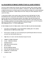
The stroke setting is important for the proper operation of the machine. If this setting has changed,
the machine may over-travel and cause the cylinder to "bottom out". This continued condition will
eventually cause the starter overload to open. It can also cause the hydraulic oil to overheat and damage
hydraulic system components. A slight change in the stroke setting can result in inadequate stroke to
operate the tooling.
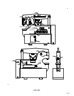
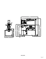
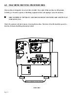
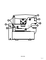
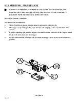
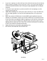
A check of the machine’s stroke setting is made at the punch station; SEE FIGURE 5 ON THE
FOLLOWING PAGE. Set the stroke control handles (A) out to their farthest position. Turn the
selector switch (G) to the START position and power the machine. Then place this switch in the
SHEAR position. Measure the distance from the top of the punch bolster to the bottom of the punch
ram. The distance should be 9-1/32 inches (229mm). Turn the selector switch to the PUNCH position
and measure the distance. The distance should be 6-25/32 inches (172mm).
These dimensions are are + or - 1/16 of
an inch (3mm).
IF THE STROKE IS OUT OF THESE LIMITS, THEN USE THE FOLLOWING PROCEDURE:
1.
Loosen the two mounting plate screws (D) that hold the mounting plate to the machine.
SEE FIGURE 5 ON THE FOLLOWING PAGE.
2.
Move the plate vertically, up or down. Moving the plate up will bring the distance down and a
movement down will bring the distance up.
3.
Tighten the screws and re-check the dimensions. Repeat, if needed.
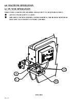
A.
STROKE CONTROL HANDLES
B.
SCALE - STROKE CONTROL
C.
METERING BOSS
D.
MOUNTING PLATE SCREWS
E.
JOG CONTROL
F.
JOG/RUN/PROBE SWITCH
G.
PUNCH/START/SHEAR SWITCH
H.
EMERGENCY STOP SWITCH
I.
START BUTTON
4.6 MACHINE STROKE INSPECTION & ADJUSTMENT
Содержание 9012-24M
Страница 10: ...Page 9 FIGURE 1 ...
Страница 12: ...Page 11 FIGURE 2 ...
Страница 16: ...Page 15 FIGURE 4A ...
Страница 17: ...Page 16 FIGURE 4B ...
Страница 18: ...Page 17 FIGURE 4C ...
Страница 22: ...Page 21 FIGURE 6 ...
Страница 24: ...Page 23 FIGURE 7 ...
Страница 35: ...Page 34 THIS PAGE LEFT BLANK INTENTIONALLY ...
Страница 40: ...Page 39 FIGURE 15 ...
Страница 42: ...Page 41 FIGURE 16 ...
Страница 48: ...Page 47 FIGURE 20 ...
Страница 54: ...Page 53 FIGURE 24 ...
Страница 56: ...Page 55 FIGURE 25 ...
Страница 62: ...Page 61 FIGURE 27 ...
Страница 66: ...Page 65 FIGURE 29 ...
Страница 68: ...Page 67 FIGURE 30 ...
Страница 74: ...Page 73 FIGURE 32 ...
Страница 78: ...Page 77 FIGURE 34 ...
Страница 80: ...Page 79 FIGURE 35 ...
Страница 82: ...Page 81 FIGURE 36 ...
Страница 84: ...Page 83 FIGURE 37 ...
Страница 86: ...Page 85 FIGURE 38 ...
Страница 90: ...Page 89 FIGURE 41 ...
Страница 92: ...Page 91 FIGURE 42 ...
Страница 93: ...Page 92 FIGURE 43 ...
Страница 96: ...Page 95 THIS PAGE LEFT BLANK INTENTIONALLY ...
Страница 98: ...Page 97 FIGURE 46 ...
Страница 100: ...Page 99 FIGURE 47 ...