


Page 27
HOLE DIAMETER
METAL
GAUGE
THICKNESS
INCHES
1/8
.125
3/16
.1875
1/4
.250
5/16
.3125
3/8
.375
7/16
.4375
1/2
.500
9/16
.5625
5/8
.625
11/16
.6875
3/4
.750
13/16
.8125
7/8
.875
15/16
.9375
1
1.00
28
.015
26
.018
24
.024
22
.030
20
.036
18
.048
16
.060
14
.075
12
.105
10
.135
.157
.188
.250
.375
.500
.625
.750
1.00
5/32
3/16
1/4
3/8
1/2
5/8
3/4
1
.2
.2
.3
.2
.2
.3
.4
.4
.4
.6
.5
.7
.6
.9
.7
1.0
.7
1.2
.8
1.3
.9
1.5
1.0
1.6
1.1
1.8
1.2
1.9
1.3
2.1
2.2
2.4
.4
.4
.5
.6
.7
.8
.9
1.0
1.1
1.1
1.2
1.3
1.4
.4
.5
.6
.7
.8
.9
1.1
1.2
1.3
1.4
1.5
1.6
.7
.9
1.1
1.2
1.4
1.6
1.8
2.1
2.3
2.5
2.6
2.8
.9
1.2
1.4
1.6
1.9
2.1
2.4
2.6
2.8
3.1
3.3
3.5
3.8
1.2
1.5
1.8
2.1
2.3
2.6
2.9
3.2
3.5
3.8
4.1
4.4
4.7
1.5
1.8
2.2
2.6
2.9
3.3
3.7
4.0
4.4
4.8
5.1
5.5
5.9
2.1
2.6
3.1
3.6
4.1
4.6
5.1
5.7
6.2
6.7
7.2
7.7
8.2
2.6
3.3
4.0
4.6
5.3
5.9
6.6
7.3
7.9
8.6
9.2
9.9
10.6
3.1
3.8
4.6
5.4
6.1
6.9
7.7
8.4
9.2
10.0
10.7
11.5
12.3
3.7
4.6
5.5
6.4
7.4
8.3
9.2
10.1
11.0
12.0
12.9
13.8
14.8
4.9
6.1
7.4
8.6
9.8
11.1
12.3
13.5
14.7
16.0
17.2
18.4
19.7
.5
.7
.9
1.1
1.5
2.0
2.3
2.8
.4
.5
.6
.7
1.0
1.3
.3
1.8
1.9
1.9
11.1
12.8
14.8
16.5
18.5
20.2
22.1
23.8
25.8
27.5
29.5
19.7
22.0
24.6
26.9
29.5
31.8
34.4
36.8
39.4
33.7
36.9
39.9
43.0
46.0
49.2
44.3
47.7
51.7
55.2
59.0
80.0
30.8
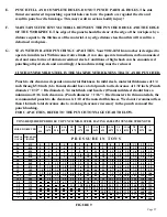
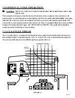
P R E S S U R E I N T O N S
TONS REQUIRED PER HOLE TO PUNCH MILD STEEL HAVING 65,000 PSI TENSILE STRENGTH
E.
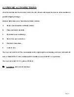
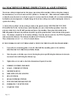
PUNCH FULL AND COMPLETE HOLES. DO NOT PUNCH PARTIAL HOLES. The side
thrust encountered in punching a partial hole can force the punch over against the die and
result in punch or die breakage. This may result in serious bodily injury!
F.
MAINTAIN SUFFICIENT MATERIAL BETWEEN THE PUNCHED HOLE AND THE EDGE
OF THE WORKPIECE. The edge of the punch should be clear of the edge of the workpiece by a
distance equal to the thickness of the material. Any edge distance less than this will result in a
deformed workpiece.
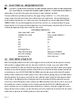
G.
STAY WITHIN RATED PUNCHING CAPACITIES. Your 9012-24M Ironworker is designed to
operate in mild steel. Within conservative limits, it can also operate in medium, carbon annealed
steel and some forms of abrasion resistant steels. Conditions of high shock can be encountered
punching alloyed steels and accordingly, the machine rating must be reduced.
1 INCH (25MM) MILD STEEL IS THE MAXIMUM THICKNESS THAT CAN BE PUNCHED.
Punch to die clearance depends on material thickness. In mild steels, material thicknesses of 1/4
inch through 5/8 inch (6 to 16mm) should have a total punch to die clearance of 1/32 inch. (Punch
di1/32" = Die diameter). 3/4 inch thick and heavier (19mm) mild steel should have a
minimum of 1/16 inch clearance. (Punch di 1/16" = Die diameter.) In thin materials, the
recommended punch to die clearance is 1/10 of the material thickness. We do not recommend less
than 1/64 inch total clearance due to working clearances necessary in the punch ram and the
punch bushing.
FOR CAPACITIES, REFER TO THE PUNCH TONNAGE CHART BELOW.
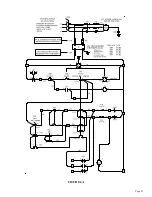
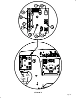
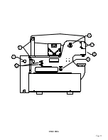
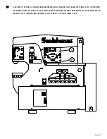
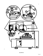
FIGURE 9
Содержание 9012-24M
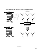
Страница 10: ...Page 9 FIGURE 1 ...
Страница 12: ...Page 11 FIGURE 2 ...
Страница 16: ...Page 15 FIGURE 4A ...
Страница 17: ...Page 16 FIGURE 4B ...
Страница 18: ...Page 17 FIGURE 4C ...
Страница 22: ...Page 21 FIGURE 6 ...
Страница 24: ...Page 23 FIGURE 7 ...
Страница 35: ...Page 34 THIS PAGE LEFT BLANK INTENTIONALLY ...
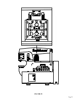
Страница 40: ...Page 39 FIGURE 15 ...
Страница 42: ...Page 41 FIGURE 16 ...
Страница 48: ...Page 47 FIGURE 20 ...
Страница 54: ...Page 53 FIGURE 24 ...
Страница 56: ...Page 55 FIGURE 25 ...
Страница 62: ...Page 61 FIGURE 27 ...
Страница 66: ...Page 65 FIGURE 29 ...
Страница 68: ...Page 67 FIGURE 30 ...
Страница 74: ...Page 73 FIGURE 32 ...
Страница 78: ...Page 77 FIGURE 34 ...
Страница 80: ...Page 79 FIGURE 35 ...
Страница 82: ...Page 81 FIGURE 36 ...
Страница 84: ...Page 83 FIGURE 37 ...
Страница 86: ...Page 85 FIGURE 38 ...
Страница 90: ...Page 89 FIGURE 41 ...
Страница 92: ...Page 91 FIGURE 42 ...
Страница 93: ...Page 92 FIGURE 43 ...
Страница 96: ...Page 95 THIS PAGE LEFT BLANK INTENTIONALLY ...
Страница 98: ...Page 97 FIGURE 46 ...
Страница 100: ...Page 99 FIGURE 47 ...