


Page 32
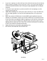
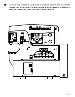
6.2B SHEAR BLADE ADJUSTMENT PROCEDURE
(SERIAL #'S 21601M & UP)
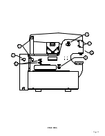
SEE FIGURE 12 ON THE FOLLOWING PAGE.
1.
Place the selector switch in the SHEAR position and allow the arms to raise completely.
2.
Crank the hold-down devise all the way up and remove the shear table.
3.
To remove the shear table, loosen the jam nut (F) on the bolts (C) and remove the bolt. Remove
the lower blade bolts (E) and back the adjustment screws (D) out.
4.
Remove the lower blade.
5.
Power the machine and place the selector switch in the PUNCH position. Allow the arm to travel
to its full down position. Turn the power off.
6.
Rotate or replace the shear blade on the arm.
7.
Rotate or replace the lower blade and start the socket head retaining bolts (E).
8.
Place a shim with the desired clearance between the upper and lower blades.
9.
Adjust the lower blade to the top blade, with the upper adjusting screws (D), about 1/8 of a turn
past resistance.
10.
Tighten the bolts (E) to 1/4 a turn past resistance.
11.
Adjust the lower adjusting screws (D) up to the blade and then, tighten all of the bolts, starting
with the blade bolts (E) and then, the adjusting screws (D).
12.
CAUTION: THE BLADES MUST BE ADJUSTED PARALLEL TO EACH OTHER, vertically or
with the cutting edge of the lower blade at a slight cant towards the upper blade.
13.
Power the machine and place the selector switch in the SHEAR position. With the foot pedal,
cycle the shear down slowly, watching the blade engagement. Make sure that the blades do not
contact each other.
14.
Replace the shear table (B). If needed, the shear table can be adjusted to match the lower blade.
15.
The table is adjusted with the four screws (G).
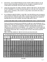
If the machine is being used to shear maximum capacities, we recommend increasing the
clearance. A clearance of five to seven percent of the material thickness is recommended.
Содержание 9012-24M
Страница 10: ...Page 9 FIGURE 1 ...
Страница 12: ...Page 11 FIGURE 2 ...
Страница 16: ...Page 15 FIGURE 4A ...
Страница 17: ...Page 16 FIGURE 4B ...
Страница 18: ...Page 17 FIGURE 4C ...
Страница 22: ...Page 21 FIGURE 6 ...
Страница 24: ...Page 23 FIGURE 7 ...
Страница 35: ...Page 34 THIS PAGE LEFT BLANK INTENTIONALLY ...
Страница 40: ...Page 39 FIGURE 15 ...
Страница 42: ...Page 41 FIGURE 16 ...
Страница 48: ...Page 47 FIGURE 20 ...
Страница 54: ...Page 53 FIGURE 24 ...
Страница 56: ...Page 55 FIGURE 25 ...
Страница 62: ...Page 61 FIGURE 27 ...
Страница 66: ...Page 65 FIGURE 29 ...
Страница 68: ...Page 67 FIGURE 30 ...
Страница 74: ...Page 73 FIGURE 32 ...
Страница 78: ...Page 77 FIGURE 34 ...
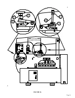
Страница 80: ...Page 79 FIGURE 35 ...
Страница 82: ...Page 81 FIGURE 36 ...
Страница 84: ...Page 83 FIGURE 37 ...
Страница 86: ...Page 85 FIGURE 38 ...
Страница 90: ...Page 89 FIGURE 41 ...
Страница 92: ...Page 91 FIGURE 42 ...
Страница 93: ...Page 92 FIGURE 43 ...
Страница 96: ...Page 95 THIS PAGE LEFT BLANK INTENTIONALLY ...
Страница 98: ...Page 97 FIGURE 46 ...
Страница 100: ...Page 99 FIGURE 47 ...