


Page 14
4.4 ELECTRICAL REQUIREMENTS
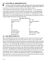
CAUTION: TO PREVENT DAMAGE TO THE MOTOR AND DANGER TO THE OPERATOR,
ALL ELECTRICAL CONNECTIONS SHOULD BE MADE BY A LICENSED ELECTRICIAN.
All machines are wired for three phase electrical power unless otherwise specified.
To insure satisfactory machine performance, the supply voltage should be (+ or -) 10% of the motor
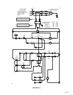
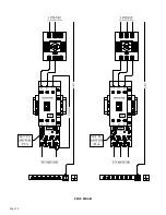
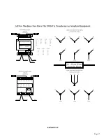
voltage rating. Check the motor data tag for full load current requirements. The electrical diagram
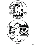
for the machine is inside the cover of the control box. The diagrams are also ON THE FOLLOWING
THREE PAGES. For electrical supply lines ten feet (3m) or shorter, we recommend at least 12 gauge,
and preferably, 10. For longer electrical supply lines, use at least 10 gauge, and preferably, 8. We do not
recommend supply lines longer than twenty five feet (7.5m).
POWER REQUIREMENTS:
Motor frame 3PH = 182T
1PH = 184T
MOTOR VOLTAGE
FULL LOAD CURRENT
(VAC)
(AMPS)
208
15.5
230
14
460
7
575
5.9
230 (Single Phase)
23.5
Motor Power Rating:
5hp Speed 1,750 RPM
KVA Power Rating:
5.6 KVA Frequency 60 HZ
Starting Current:
210% Full Load
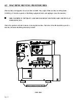
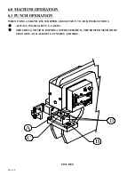
4.5 MACHINE START-UP
Before starting this machine, take time to thoroughly review the safety CD and the operator's manual.
This machine is equipped with a lock-out, disconnect switch. We strongly urge you to follow OSHA
directive CFR-1910.147 (effective 09-01-90) regarding lock-out, tag-out procedures. Before powering the
machine, be sure that all packing materials and tools have been removed from the machine and that the
work stations are clear. TO POWER THE MACHINE, place the disconnect switch in the ON position
and the selector switch in the START position. Power the machine by pushing the green START button.
Once the machine has been powered, it will not move until the selector switch has been placed in either
the PUNCH or the SHEAR position. Placing the selector switch in the PUNCH position will cause the
arms to move down. Placing the selector switch in the SHEAR position will cause the arms to move up. If
the machine does not move when the selector switch is placed in the PUNCH or SHEAR position, the
motor rotation is not correct and the electrician will have to switch two of the three supply line wires to
change the direction of rotation. Any time that the power to the machine has been turned off, the selector
switch must be placed in the START position to restart the machine.
Содержание 9012-24M
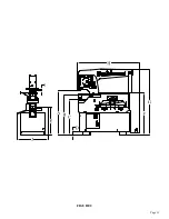
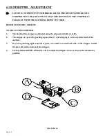
Страница 10: ...Page 9 FIGURE 1 ...
Страница 12: ...Page 11 FIGURE 2 ...
Страница 16: ...Page 15 FIGURE 4A ...
Страница 17: ...Page 16 FIGURE 4B ...
Страница 18: ...Page 17 FIGURE 4C ...
Страница 22: ...Page 21 FIGURE 6 ...
Страница 24: ...Page 23 FIGURE 7 ...
Страница 35: ...Page 34 THIS PAGE LEFT BLANK INTENTIONALLY ...
Страница 40: ...Page 39 FIGURE 15 ...
Страница 42: ...Page 41 FIGURE 16 ...
Страница 48: ...Page 47 FIGURE 20 ...
Страница 54: ...Page 53 FIGURE 24 ...
Страница 56: ...Page 55 FIGURE 25 ...
Страница 62: ...Page 61 FIGURE 27 ...
Страница 66: ...Page 65 FIGURE 29 ...
Страница 68: ...Page 67 FIGURE 30 ...
Страница 74: ...Page 73 FIGURE 32 ...
Страница 78: ...Page 77 FIGURE 34 ...
Страница 80: ...Page 79 FIGURE 35 ...
Страница 82: ...Page 81 FIGURE 36 ...
Страница 84: ...Page 83 FIGURE 37 ...
Страница 86: ...Page 85 FIGURE 38 ...
Страница 90: ...Page 89 FIGURE 41 ...
Страница 92: ...Page 91 FIGURE 42 ...
Страница 93: ...Page 92 FIGURE 43 ...
Страница 96: ...Page 95 THIS PAGE LEFT BLANK INTENTIONALLY ...
Страница 98: ...Page 97 FIGURE 46 ...
Страница 100: ...Page 99 FIGURE 47 ...


