Page 30
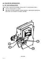
THE BASIC METHOD OF OPERATING THE BAR SHEAR CONSISTS OF SIX STEPS:
1.
Place the selector switch in the START position and power the machine.
2.
Place the selector switch in the SHEAR position.
3.
Place the material to be sheared between the shear blades.
4.
Crank the hold-down device down to the material being sheared. This prevents kick-up of the
material, which could cause injury to the operator and damage to the machine.
5.
Keep your hands clear from all moving parts.
6.
Depress the foot switch. Lubricate the blades every 10 to 15 cuts.
IN ADDITION TO THE SIX BASIC STEPS OF OPERATION, THE OPERATOR SHOULD ALSO
BE FAMILIAR WITH THE FOLLOWING:
A.
MAINTAIN PROPER BLADE CLEARANCE.
The quality of the cut is an immediate indication of the condition of the Shear Blades, the amount of
clearance between the blades or the amount of "spring-back" in the Shear Arm.
The Shear Blades are symmetrical and can be rotated to expose four (4) cutting edges.
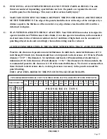
For recommended clearances, SEE FIGURE 12 ON PAGE 33.
B.
ALL CUTS SHOULD BE MADE AS FAR FROM THE ARM PIVOT AS POWER WILL
PERMIT.
The Shear Blades should contact the workpiece as flat as possible, to reduce to a minimum the amount of
"curl" on the cut-off piece. More shearing force is obtained as the operator moves the workpiece toward
the left. The machine is designed to shear mild steel rated on 65,000 tensile. The maximum capacity of the
bar shear is 1 x 8 inch (25 x 203mm) mild steel.
SEE FIGURE 11 ON THE FOLLOWING PAGE.
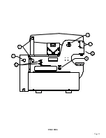
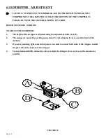
Adjustment of the shear arm is maintained on the front (operator’s) side by the pressure plate (A) and on
the rear by the rub blocks (I & J). The cylinder cover shroud must be removed to gain visual access.
USE THE FOLLOWING STEPS TO ADJUST THE SHEAR ARM:
1.
Before making these adjustments, loosen the lower blade bolts and set screws and back the lower
blade away from the upper blade. After making these adjustments, reset the blades following the
instructions IN SECTION 6.2B.
6.2A SHEAR ARM ADJUSTMENT (SER. # 21601 & UP)
Содержание 9012-24M
Страница 10: ...Page 9 FIGURE 1 ...
Страница 12: ...Page 11 FIGURE 2 ...
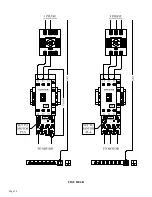
Страница 16: ...Page 15 FIGURE 4A ...
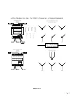
Страница 17: ...Page 16 FIGURE 4B ...
Страница 18: ...Page 17 FIGURE 4C ...
Страница 22: ...Page 21 FIGURE 6 ...
Страница 24: ...Page 23 FIGURE 7 ...
Страница 35: ...Page 34 THIS PAGE LEFT BLANK INTENTIONALLY ...
Страница 40: ...Page 39 FIGURE 15 ...
Страница 42: ...Page 41 FIGURE 16 ...
Страница 48: ...Page 47 FIGURE 20 ...
Страница 54: ...Page 53 FIGURE 24 ...
Страница 56: ...Page 55 FIGURE 25 ...
Страница 62: ...Page 61 FIGURE 27 ...
Страница 66: ...Page 65 FIGURE 29 ...
Страница 68: ...Page 67 FIGURE 30 ...
Страница 74: ...Page 73 FIGURE 32 ...
Страница 78: ...Page 77 FIGURE 34 ...
Страница 80: ...Page 79 FIGURE 35 ...
Страница 82: ...Page 81 FIGURE 36 ...
Страница 84: ...Page 83 FIGURE 37 ...
Страница 86: ...Page 85 FIGURE 38 ...
Страница 90: ...Page 89 FIGURE 41 ...
Страница 92: ...Page 91 FIGURE 42 ...
Страница 93: ...Page 92 FIGURE 43 ...
Страница 96: ...Page 95 THIS PAGE LEFT BLANK INTENTIONALLY ...
Страница 98: ...Page 97 FIGURE 46 ...
Страница 100: ...Page 99 FIGURE 47 ...

