


4-2
Loss-of-Potential, CCVT Transient Detection,
Date Code 20011205
Load-Encroachment, and Directional Element Logic
SEL-311B Instruction Manual
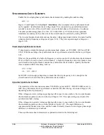
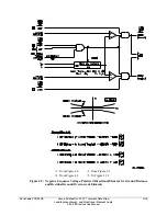
Loss-of-potential is declared (Relay Word bit LOP = logical 1) when a 10 percent drop in V
1
is
detected, with no corresponding change in I
1
or I
0
. If the LOP condition persists for 60 cycles, it
latches in. LOP resets (Relay Word bit LOP = logical 0) when V
1
returns above 50 V secondary
and V
0
is less than 5 V secondary.
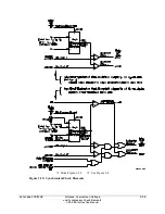
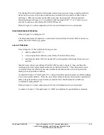
The loss-of-potential enable setting, ELOP, does not enable or disable the LOP logic. It just
routes the LOP Relay Word bit to different logic, as shown in Figure 4.1 and explained in the
remainder of this subsection.
Note that ILOP disables all distance elements (Figures 3.4 through 3.9).
LOP is disabled while 3PO is asserted (breaker open). If an input potential is lost during this
time, LOP will not assert when 3PO deasserts (breaker close) since the 10 percent drop in V
1
has
already occurred. This is the case for systems using either line-side or bus-side potential
transformers.
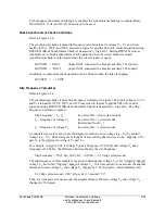
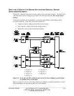
You may provide a SCADA alarm for bus-side potential transformers with the following
SEL
OGIC
expression:
SV1 = 3PO
OUT105 = !3P59 * SV1T + LOP
See Figure 3.22. Relay Word bit 3P59 asserts when A-phase, B-phase, and C-phase voltage
magnitudes are greater than setting 59P. Setting 59P should be at least 80 percent of nominal
voltage. Relay Word bit 3PO asserts when the circuit breaker is open. Set SV1PU longer than
the reclose open-time interval. In this expression, if any phase voltage is less than setting 59P
while the circuit breaker is open, or LOP is asserted, the expression is true (logical 1).
If the output is asserted, check the relay input potentials before closing the circuit breaker.
In a system using line-side potential transformers, remove SV1T from the expression. The alarm
will assert whenever the line is deenergized and will clear when the circuit breaker is closed if
system voltage is normal. If the output is asserted when the circuit breaker is closed, check the
relay input potentials.
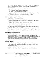
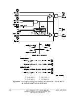
Setting ELOP = Y or Y1
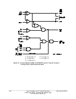
If setting ELOP = Y or Y1 and a loss-of-potential condition occurs (Relay Word bit LOP asserts
to logical 1), negative-sequence voltage-polarized, zero-sequence voltage-polarized, and positive-
sequence voltage-polarized directional elements, plus all distance elements, are disabled by relay
word bit ILOP (see Figure 4.9, Figure 4.10, Figure 4.14, Figure 4.15, and Figure 3.4 through
Figure 3.9). The loss-of-potential condition makes these voltage-polarized directional elements
and distance elements unreliable. Thus, they are disabled. The overcurrent elements controlled
by these voltage-polarized directional elements are disabled also (unless overridden by conditions
explained in the following
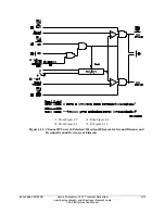
Setting ELOP = Y
discussion).
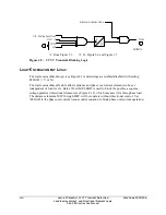
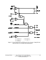
In Figure 4.11, the assertion of ILOP is an additional enable for the channel IP current-polarized
directional element. This directional element is not voltage polarized and is automatically
enabled during LOP conditions if ELOP = Y or Y1.
Содержание SEL-311B
Страница 6: ......
Страница 8: ......
Страница 10: ......
Страница 24: ......
Страница 26: ......
Страница 122: ......
Страница 124: ......
Страница 138: ......
Страница 168: ......
Страница 172: ......
Страница 254: ......
Страница 282: ......
Страница 306: ......
Страница 348: ......
Страница 364: ......
Страница 366: ......
Страница 448: ......
Страница 460: ......
Страница 466: ......
Страница 476: ......
Страница 482: ......
Страница 494: ......
Страница 500: ......
Страница 522: ......
Страница 526: ......
Страница 528: ......
Страница 534: ......
Страница 536: ......
Страница 550: ......
Страница 570: ......
Страница 586: ......
Страница 600: ......


