Date Code 20011205
Trip and Target Logic
5-11
SEL-311A Instruction Manual
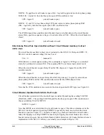
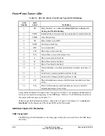
The TRIP target LED is especially helpful in providing front-panel indication for tripping that
does not involve protection elements. If the trip is not a protection element generated trip, none
of the target LEDs illuminate (3 through 5 and 7 through 16), but the TRIP target LED still
illuminates. Thus, tripping via the front-panel local control (local bits) or serial port (remote bits
or OPEN command) is indicated only by the illumination of the TRIP target LED.
TIME Target LED
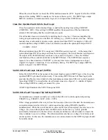
The TIME target LED illuminates at the rising edge of trip if SEL
OGIC
control equation setting
FAULT has been asserted for more than 3 cycles. FAULT is usually set with distance and
time-overcurrent element pickups (e.g., FAULT = 51G + M2P + Z2G) to detect fault inception.
If tripping occurs more than 3 cycles after fault inception, the TIME target illuminates.
SEL
OGIC
control equation setting FAULT also controls max./min. metering. If FAULT is
asserted, maximum/minimum metering is blocked (see
Maximum/Minimum Metering
in
Section 8: Breaker Monitor and Metering Functions
). Fault current values are not to be
accrued as maximum current values in maximum/minimum metering.
DT Target LED
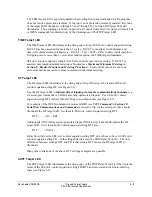
The DT target LED illuminates at the rising edge of trip if the trip is the result of SEL
OGIC
control equation setting DT (see Figure 5.1).
Use the DT target LED to
indicate direct tripping via remote communications channels
(e.g.,
via serial port commands or SCADA asserting optoisolated inputs). Use SEL
OGIC
control
equation setting DTT (Direct Transfer Trip) to accomplish this (see Figure 5.1).
For example, if the OPEN command or remote bit RB1 (see
CON Command
in
Section 10:
Serial Port Communications and Commands
) are used to trip via the serial port, they should
illuminate the DT target LED. Set them in SEL
OGIC
control equation setting DTT:
DTT = … + OC + RB1
Additionally, if SCADA asserts optoisolated input IN104 to trip, it should illuminate the DT
target LED. Set it in SEL
OGIC
control equation setting DTT also:
DTT = … + IN104 + …
Relay Word bits set in SEL
OGIC
control equation setting DTT do not have to be set in SEL
OGIC
control equation setting TR—both settings directly assert the TRIP Relay Word bit. The only
difference between settings DTT and TR is that setting DTT causes the DT target LED to
illuminate.
Many other variations of the above DTT settings examples are possible.
SOTF Target LED
The SOTF target LED illuminates at the rising edge of the TRIP Relay Word bit if the trip is the
result of the SEL
OGIC
control equation setting TRSOTF and associated switch-onto-fault trip
Содержание SEL-311A
Страница 6: ......
Страница 8: ......
Страница 10: ......
Страница 24: ......
Страница 40: ......
Страница 66: ......
Страница 96: ......
Страница 98: ......
Страница 112: ......
Страница 114: ......
Страница 122: ......
Страница 170: ......
Страница 202: ......
Страница 204: ......
Страница 246: ......
Страница 248: ......
Страница 286: ......
Страница 290: ......
Страница 304: ......
Страница 306: ......
Страница 334: ......
Страница 384: ......
Страница 386: ......
Страница 394: ......
Страница 398: ......
Страница 402: ......
Страница 404: ......
Страница 410: ......
Страница 412: ......
Страница 426: ......
Страница 444: ......
Страница 460: ......
Страница 474: ......


