Page 8
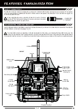
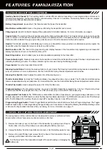
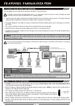
Auxiliary Switch (Channel 3):
The Auxiliary Switch controls different options, depending on your programming preferences. In
the default configuration, the Auxiliary Switch controls Auxiliary Channel 3. In addition, the Auxiliary Switch is used to program
and control the different Mixes that are available.
Battery Compartment:
Houses the 4 'AA' Alkaline cells that power the transmitter.
Bind Button and Bind LED:
Used in the process of Binding the transmitter and receiver.
Charging Jack:
Used for onboard charging of the optional Ni-Cd or Ni-MH batteries. For more information, see page 9.
Coaxial Cable:
The portion of the antenna that extends the Antenna Reception Wire. The Coaxial Cable can be bent into gentle
curves, however, do not bend the Coaxial Cable acutely, or repeatedly bend it, or the antenna core can be damaged. The Coaxial
Cable should be installed through a nylon tube (antenna tube) in the vertical position for the best reception.
Handle:
The Handle provides a comfortable way to carry your transmitter. It also provides a comfortable angle to program the
transmitter when the transmitter is laid on its back on a flat surface.
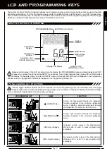
Multi-Function LCD:
The heart of the programming and display features of the transmitter. All programming and transmitter
display functions are shown on the Multi-Function LCD.
Neck Strap Anchor:
Used to attach your neck strap (available separately) to the transmitter.
Power Indicator Light:
Flashes slowly when the transmitter is turned ON and transmitting a signal. Flashes in rapid succession
indicating that Mixing is Active. The Power Indicator Light is also used during the Binding process.
Power Switch:
Turns the transmitter ON and OFF.
Steering Control Stick:
Controls the steering function of your model. The Steering Control Stick spring tension is adjustable to
suit your preference. For more information, see the Control Stick Spring Tension Adjustment section below.
Steering Trim Switch:
Used to adjust the center trim of the steering servo.
Throttle Control Stick:
Controls the Throttle and Brake (if equipped) functions of your model. The Throttle Control Stick spring
tension is adjustable to suit your preference. For more information, see the Control Stick Spring Tension Adjustment section below.
Throttle Trim Switch:
Used to adjust the center trim of the throttle servo.
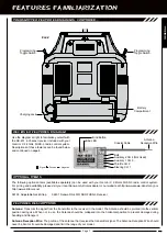
Programming Keys:
The Programming Keys are used to facilitate transmitter programming. The four Programming Keys
consist of two MENU Keys (Right and Left), one +/INC (Increase) Key, and one DEC/- (Decrease) Key.
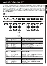
Programmable Trim Switch:
The TRM Switch controls different options, depending on your programming preferences. In the
default configuration, the TRM Switch controls the Steering Dual Rate adjustment. The TRM Switch can also control Throttle High
EPA, Throttle Brake EPA, Auxiliary Channel 3 High EPA, Auxiliary Channel 3 Low EPA, and more.
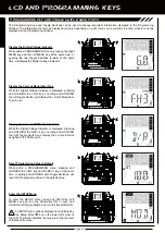
Programming Toggle Switch:
The two Toggle Switches perform the same functions as the four Programming Keys. The Toggle
Switches make it easy to make programming changes during use. For example, to change the Steering Dual Rate percentage value
or Activate the Dig and Burn functions while your driving.
For more information, see page 11.
FEaTURES FaMiLiaRizaTiOn
FEaTURES DEScRiPTiOnS, cOnTinUED....
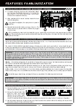
cOnTROL STick SPRing TEnSiOn aDjUSTMEnT
The spring tension of the control sticks can be adjusted to suit your preference. Some
drivers prefer a firmer feel and some drivers prefer a softer feel.
1) Remove the battery cover on the back of the transmitter by pushing down firmly on
the two tabs in the top of the battery cover and pulling the battery cover out.
2) Unplug the battery from the transmitter and remove it. Set the battery aside for now.
3) Remove the eight Phillips head screws from the back of the transmitter, then very
carefully pull the back half of the transmitter off.
Pull the back half of the transmitter straight off to avoid bending or damaging the
battery pins.
Содержание Gemini X
Страница 1: ...Page 1 ...
Страница 55: ...Page 55 NOTES ...


