Page 40
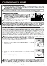
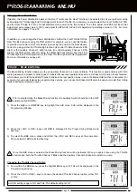
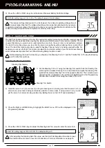
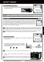
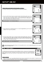
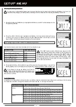
When the Binding procedure is successful, the Bind LED will stay solid blue and the Power Indicator Light will flash slowly
when both the transmitter and receiver are turned ON. If the Bind LED on the receiver is flashing rapidly, the transmitter and
receiver are not paired. In this case, turn both the transmitter and receiver OFF, then repeat the Binding procedure.
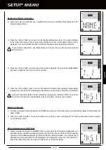
5) After verifying that the Binding process is complete (solid blue Bind LED on the receiver) and the servos operating normally,
press either the Right MENU key or the Left MENU key to return to the BIND menu.
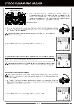
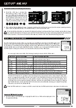
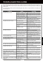
4) Press the +/INC key a second time.
PUSH DEC will flash. Press the DEC/-
key once. BIND will be displayed in the
Programming Window, the LCD and the
Power Indicator Light will flash, then the
Bind LED on the receiver will turn solid
indicating the Binding process is complete.
Transmitter and Receiver Binding, Continued....
SETUP MEnU
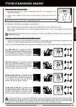
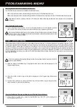
The Trim Switch Assign function allows you to assign several different operations to the TRM switch. This
allows you to easily control during use a specific Auxiliary function that you've assigned to the TRM switch.
For example, you could assign the Step Auxiliary function to the TRM switch and control your glow-powered
model's needle valve or your boat's adjustable trim step. In addition, you can change the Step Resolution of
the TRM switch to change how far the servo travels with each press of the TRM switch.
TRM - TRiM SwiTcH aSSign
You can assign and control ONE of the following Auxiliary functions with the TRM switch:
FuNCTION
FuNCTION NAME
FuNCTION DESCRIPTION
D/R
TH_HI
TH_BR
3C_HI
3C_LO
3_SUB
P_AUX
S_AUX
S
teering
D
ual
r
ate
t
hrottle
h
igh
ePa
t
hrottle
b
raKe
ePa
a
uxiliary
c
hannel
3 h
igh
ePa
a
uxiliary
c
hannel
3 l
ow
ePa
a
uxiliary
c
hannel
3 S
ub
-t
rim
*
P
oint
a
uxiliary
P
rogram
S
teP
a
uxiliary
P
rogram
c
ontrolS
S
teering
D
ual
r
ate
c
ontrolS
t
hrottle
h
igh
S
iDe
e
nD
P
oint
a
DjuStment
c
ontrolS
t
hrottle
b
raKe
S
iDe
e
nD
P
oint
a
DjuStment
c
ontrolS
a
uxiliary
c
hannel
3 h
igh
S
iDe
e
nD
P
oint
a
DjuStment
c
ontrolS
a
uxiliary
c
hannel
3 l
ow
S
iDe
e
nD
P
oint
a
DjuStment
c
ontrolS
a
uxiliary
c
hannel
3 S
ub
-t
rim
c
ontrolS
P
rogrammeD
P
oint
a
uxiliary
S
ervo
m
ovement
c
ontrol
P
rogrammeD
S
teP
a
uxiliary
S
ervo
m
ovement
*This Sub-Trim function is only effective when Auxiliary Channel 3 is used as a mixer. In the default configuration,
any servo plugged into Auxiliary Channel 3 will move TO and FROM the HIGH and LOW positions only. It is not
a proportional channel that features a center position. However, when being used as a mixer, for example, when
controlling front and rear steering, Auxiliary Channel 3 will react as a proportional channel, just like the Steering
and Throttle channels. In this case this Sub-Trim function will work as intended, allowing you to adjust the Auxiliary
Channel 3 servo center trim independently.
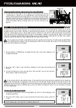
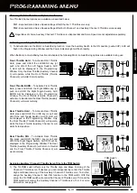
Assigning TRM Switch Functions
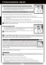
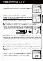
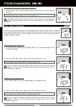
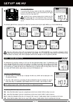
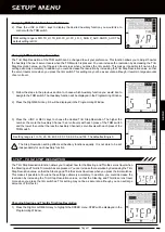
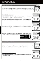
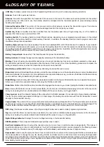
1) Press the Right or Left MENU key to highlight the EXP menu. TRM will be displayed in the
Programming Window.
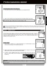
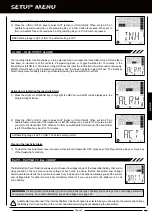
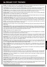
Press the TRM switch up to increase a function value and press the TRM switch down to decrease a function value.
Содержание Gemini X
Страница 1: ...Page 1 ...
Страница 55: ...Page 55 NOTES ...

