Operations & Installation
2-38
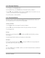
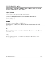
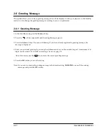
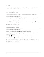
2-9-6 Changing PIN (Personal Identification Number)
The PIN is required when you access
System
menus. The PIN is preset to Ô0000Õ at factory. You can change the
PIN code.
1. In the Standby mode, press the
Menu
soft key.
2. Press the
soft key repeatedly until
System
appears, then press the
Select
soft key.
3. Enter the PIN code, then press the
OK
soft key.
4. Press the
soft key repeatedly until
Change PIN
appears, then press the
Select
soft key.
5.
New PIN [ ]
is displayed. Enter a new PIN code, then press the
OK
soft key. The LCD window does not
display the PIN code you entered in order to maintain secrecy.
Note:
It must be 4 digits. If you make a mistake, you can correct the number by using the
key.
6. Enter the new PIN code again to confirm the number, then press the
OK
soft key.
Notes:
¥ If you enter a different number from the new code, the phone sounds an error beep, and returns to the
previous screen.
¥ If you change the PIN code and then forget it, you will have to contact your local service center.
¥ If you want to exit from the Change PIN mode while changing PIN, press the
Exit
soft key.
C
Содержание SP-R6100
Страница 3: ......
Страница 50: ...Exploded View Parts List 3 4 3 4 SP R6100 BASE Exploded View 1 7 8 9 10 13 14 15 16 2 3 11 9 12 4 5 6 ...
Страница 52: ...Exploded View Parts List 3 6 3 6 SP R6100 CHARGER Exploded View 6 8 7 1 2 3 4 5 9 ...
Страница 54: ...Exploded View Parts List 3 8 SP R6100 PACKING Exploded View 3 8 3 7 4 1 5 8 2 6 9 ...
Страница 67: ...6 1 6 PCB Diagrams 6 1 SP R6100 Base PCB I ...
Страница 68: ...PCD Diagrams ...
Страница 69: ...6 2 SP R6100 Base PCB II 6 2 ...
Страница 70: ...PCD Diagrams ...
Страница 71: ...6 3 SP R6100 Handy PCB I 6 3 ...
Страница 72: ...PCD Diagrams ...
Страница 73: ...6 4 SP R6100 Handy PCB II 6 4 ...
Страница 74: ...PCD Diagrams ...
Страница 75: ...6 5 SP R6100 Key PCB I PCD Diagrams 6 5 ...
Страница 76: ...6 6 SP R6100 Key PCB II PCB Diagrams 6 6 ...
Страница 77: ...6 7 SP R6100 Charger PCB I 6 7 PCD Diagrams ...
Страница 78: ...6 8 SP R6100 Charger PCB II PCB Diagrams 6 8 ...
Страница 79: ...Schematic Diagrams 7 1 7 Schematic Diagrams 7 1 SP R6100 Hand LOGIC ...
Страница 80: ...Schematic Diagrams 7 2 7 2 SP R6100 Hand RF SL18 9 SL55 SL18 9 SL19 SL7 SL9 5 SL18 9 SL18 9 SL5 5 SL7 5 SL5 ...
Страница 81: ...Schematic Diagrams 7 3 7 3 SP R6100 BASE LOGIC ...
Страница 82: ...Schematic Diagrams 7 4 7 4 SP R6100 Base CLIP ...
Страница 84: ...Schematic Diagrams 7 6 HAND KEY 7 6 ...
Страница 85: ...Schematic Diagrams 7 7 CHRGER 7 7 ...
Страница 88: ...Samsung Electronics Co Ltd ELECTRONICS ...

