Operations & Installation
2-8
2-1-6 Turning the Handset On/Off
When you place the handset in the base unit to charge it, the handset automatically turns on. To turn the
handset on or off in Standby mode, follow these steps:
1. To turn on the handset when the display is off, press
key.
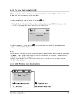
The display shows the handset and base number, and the greeting message SAMSUNG as shown below.
(To change the greeting, see page 42) The phone is now ready for use.
2. To turn the handset off, press and hold
key for about three seconds until the power-off message
appears in the display. The display turns off.
Notes:
¥ If you purchase an additional handset, you must register the handset to a base. If not, the display shows
Fail
to Register
when you turn it on and only two soft keys work to allow you to register the handset. Refer to
ÔRegistering a New HandsetÕ on page 54.
¥ Nothing will appear in the LCD window when battery power is very low. You should fully charge the
handset before operation.
INT
INT
H S ( 1 ) B S ( 1 )
S A M S U N G
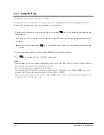
2-1-7 LCD Window Icon Descriptions
Signal Strength icon
Line icon
Vibration icon
Battery status icon
H S ( 1 ) B S ( 1 )
S A M S U N G
Содержание SP-R6100
Страница 3: ......
Страница 50: ...Exploded View Parts List 3 4 3 4 SP R6100 BASE Exploded View 1 7 8 9 10 13 14 15 16 2 3 11 9 12 4 5 6 ...
Страница 52: ...Exploded View Parts List 3 6 3 6 SP R6100 CHARGER Exploded View 6 8 7 1 2 3 4 5 9 ...
Страница 54: ...Exploded View Parts List 3 8 SP R6100 PACKING Exploded View 3 8 3 7 4 1 5 8 2 6 9 ...
Страница 67: ...6 1 6 PCB Diagrams 6 1 SP R6100 Base PCB I ...
Страница 68: ...PCD Diagrams ...
Страница 69: ...6 2 SP R6100 Base PCB II 6 2 ...
Страница 70: ...PCD Diagrams ...
Страница 71: ...6 3 SP R6100 Handy PCB I 6 3 ...
Страница 72: ...PCD Diagrams ...
Страница 73: ...6 4 SP R6100 Handy PCB II 6 4 ...
Страница 74: ...PCD Diagrams ...
Страница 75: ...6 5 SP R6100 Key PCB I PCD Diagrams 6 5 ...
Страница 76: ...6 6 SP R6100 Key PCB II PCB Diagrams 6 6 ...
Страница 77: ...6 7 SP R6100 Charger PCB I 6 7 PCD Diagrams ...
Страница 78: ...6 8 SP R6100 Charger PCB II PCB Diagrams 6 8 ...
Страница 79: ...Schematic Diagrams 7 1 7 Schematic Diagrams 7 1 SP R6100 Hand LOGIC ...
Страница 80: ...Schematic Diagrams 7 2 7 2 SP R6100 Hand RF SL18 9 SL55 SL18 9 SL19 SL7 SL9 5 SL18 9 SL18 9 SL5 5 SL7 5 SL5 ...
Страница 81: ...Schematic Diagrams 7 3 7 3 SP R6100 BASE LOGIC ...
Страница 82: ...Schematic Diagrams 7 4 7 4 SP R6100 Base CLIP ...
Страница 84: ...Schematic Diagrams 7 6 HAND KEY 7 6 ...
Страница 85: ...Schematic Diagrams 7 7 CHRGER 7 7 ...
Страница 88: ...Samsung Electronics Co Ltd ELECTRONICS ...


