Disassembly and Reassembly
Samsung Electronics
3-39
No
Parts
Procedure
Remark
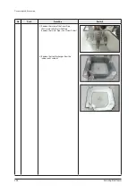
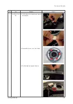
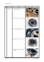
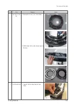
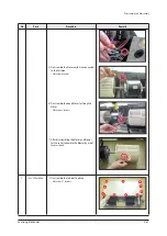
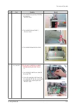
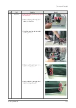
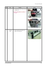
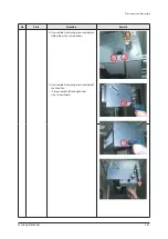
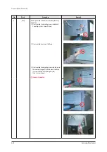
3) Disassemble the Support Evap. LF that fixes
the Evaporator.
– Unscrew 2 screws
4) Disassemble the Support Evap RH.
– Unscrew 2 screws
5) Disassemble the Evaporator form the set.
4
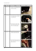
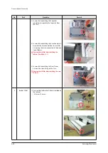
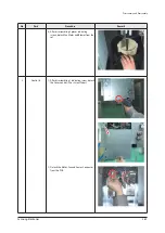
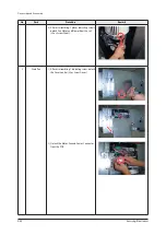
Ass'y Control In
The Control In should be disassembled
after disassembling the Cover Control
1-3).
1) Disassemble all Control Wires connected to
the inside of PCB.
2) In case of disassembling the PCB separately,
disassemble the PCB from the case with push-
ing the hook after unscrewing the screw.
– Unscrew 1 screw
Содержание AM160FNBFEB/EU
Страница 283: ...PCB Diagram and Parts List Samsung Electronics 5 7 5 1 4 360 cassette MAIN PCB 1 2 3 4 5 6 7 8 9 10 11 12 13 ...
Страница 295: ...PCB Diagram and Parts List Samsung Electronics 5 19 5 1 10 Duct type HSP BLDC PCB 1 2 3 4 ...
Страница 297: ...PCB Diagram and Parts List Samsung Electronics 5 21 5 1 11 Duct type Super 1 2 3 5 4 6 9 10 11 12 13 14 15 16 7 8 ...
Страница 299: ...PCB Diagram and Parts List Samsung Electronics 5 23 5 1 12 Celing type 1 2 3 4 5 6 7 19 18 9 10 11 12 17 15 14 13 8 ...
Страница 307: ...PCB Diagram and Parts List Samsung Electronics 5 31 5 1 15 Wall Mounted type A3050 MAIN 1 2 4 5 6 7 8 10 11 9 12 13 3 ...
Страница 318: ...Wiring Diagram 6 4 Samsung Electronics 6 1 4 BIG Duct This Document can not be used without Samsung s authorization ...
Страница 319: ...Wiring Diagram Samsung Electronics 6 5 6 1 5 Ceiling This Document can not be used without Samsung s authorization ...
Страница 320: ...Wiring Diagram 6 6 Samsung Electronics 6 1 6 Console This Document can not be used without Samsung s authorization ...
Страница 328: ...Wiring Diagram 6 14 Samsung Electronics 6 1 14 ERV Plus This Document can not be used without Samsung s authorization ...


