T
ro
u
b
l
eshooting
4-7
2
S
ams
u
ng
El
ectronics
4-4-
2
8 C
o
mmun
i
c
atio
n E
rror
b
et
w
ee
n MCU
a
n
d
O
u
tdoor
Un
it
a
f
ter
T
ra
ck
i
ng
is
C
o
mpl
eted
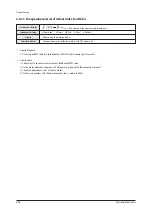
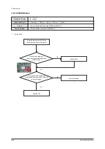
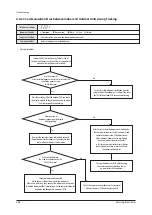
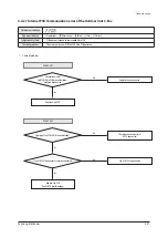
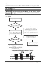
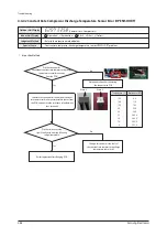
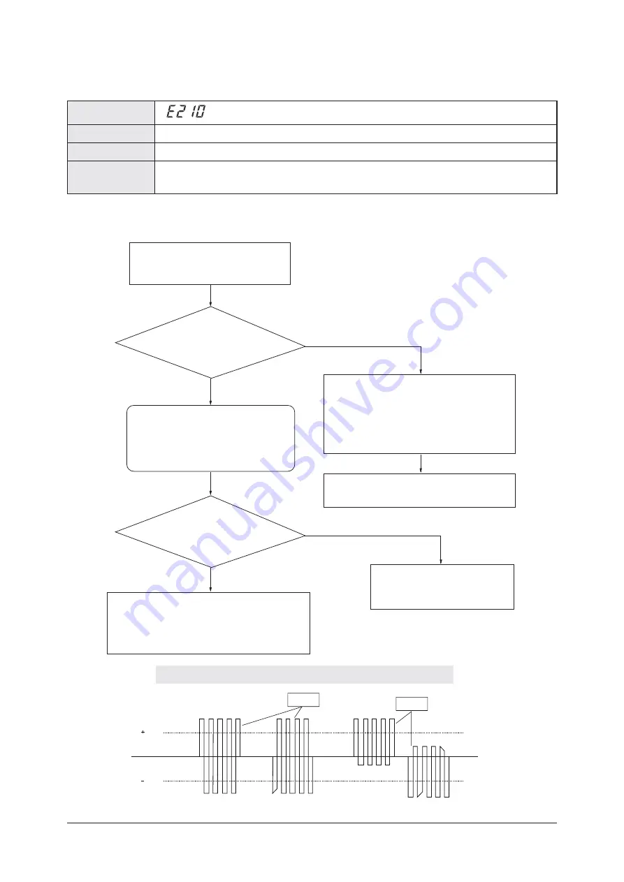
t$PNNVOJDBUJPOFSSPSCFUXFFOJOEPPSBOEPVUEPPSVOJUTBOETFUVQFSSPSPGJOEPPSVOJUJOTUBMMBUJPORVBOUJUZ
set
u
p
switch
Judgment Method
Special Cause
t0VUEPPSVOJUJTVOBCMFUPDPNNVOJDBUFGPSUXPPSNPSFNJOVUFTEVSJOHPQFSBUJPO OPSFDFQUJPOPGSFMPDBUJPO
Outdoor Unit Display
1
.
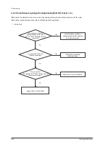
I
nspection
Method
Indoor Unit Display
-
Y
es
Press
the
P
CB
reset
ke
y (K
3)
of
the
o
u
tdoor
u
nit
and
check
the
disp
l
a
y
mod
ul
e.
I
s
the
v
o
l
tage
between
the
2
cab
l
es
a
s
qu
are
wa
v
e
with
D
C±0
.
7V
or
more
?
I
s
there
no
M
CU
response
at
a
ll
on
the
disp
l
a
y
mod
ul
e
d
u
ring
the
tracking
?
Remo
v
e
the
comm
u
nication
cab
l
e
which
connects
the
o
u
tdoor
u
nit
to
the
M
CU,
and
meas
u
re
the
2
cab
l
es
of
the
o
u
tdoor
u
nit
with
a
scope.
C
onnect
the
comm
u
nication
cab
l
e
which
connects
the
o
u
tdoor
u
nit
to
the
M
CU
again
,
remo
v
e
a
ll
comm
u
nication
connectors
from
the
M
CU
P
CB
.
C
onnect
each
u
nit
one
b
y
one
,
and
find
the
M
CU
which
interferes
with
comm
u
nication
to
check
and
change
the
M
CU
P
CB
.
A
fter
two
min
u
tes
,
find
the
M
CU
which
disp
l
a
y
s
the
comm
u
nication
error
and
check
if
the
P
CB
address
settings
are
o
v
er
l
apped.
(A
comm
u
nication
error
occ
u
rs
if
the
indoor
u
nit
addresses
are
o
v
er
l
apped.)
- I
n
this
case
,
a
comm
u
nication
error
wi
ll
occ
u
r
in
e
v
er
y
M
CU (
two
or
more
u
nits)
with
the
address
incorrect
ly
set.
I
nspect
the
comm
u
nication
cab
l
e
and
the
connector
of
the
o
u
tdoor
P
CB
and
then
change
the
P
CB
.
0
.
7V
0
.
7V
Good
Defective
I
f
there
is
no
pec
ul
iarit
y
in
the
address
,
check
comm
u
nication
and
then
change
the
M
CU
P
CB
.
Y
es
No
No
❈
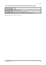
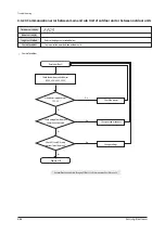
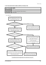
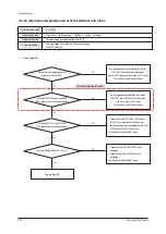
Essential Requirements before Changing PCB in Case of Communication Error: Refer to p.4-80
Содержание AM160FNBFEB/EU
Страница 283: ...PCB Diagram and Parts List Samsung Electronics 5 7 5 1 4 360 cassette MAIN PCB 1 2 3 4 5 6 7 8 9 10 11 12 13 ...
Страница 295: ...PCB Diagram and Parts List Samsung Electronics 5 19 5 1 10 Duct type HSP BLDC PCB 1 2 3 4 ...
Страница 297: ...PCB Diagram and Parts List Samsung Electronics 5 21 5 1 11 Duct type Super 1 2 3 5 4 6 9 10 11 12 13 14 15 16 7 8 ...
Страница 299: ...PCB Diagram and Parts List Samsung Electronics 5 23 5 1 12 Celing type 1 2 3 4 5 6 7 19 18 9 10 11 12 17 15 14 13 8 ...
Страница 307: ...PCB Diagram and Parts List Samsung Electronics 5 31 5 1 15 Wall Mounted type A3050 MAIN 1 2 4 5 6 7 8 10 11 9 12 13 3 ...
Страница 318: ...Wiring Diagram 6 4 Samsung Electronics 6 1 4 BIG Duct This Document can not be used without Samsung s authorization ...
Страница 319: ...Wiring Diagram Samsung Electronics 6 5 6 1 5 Ceiling This Document can not be used without Samsung s authorization ...
Страница 320: ...Wiring Diagram 6 6 Samsung Electronics 6 1 6 Console This Document can not be used without Samsung s authorization ...
Страница 328: ...Wiring Diagram 6 14 Samsung Electronics 6 1 14 ERV Plus This Document can not be used without Samsung s authorization ...

