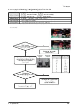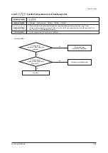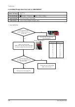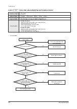
T
ro
u
b
l
eshootin
g
4-84
S
a
m
s
u
n
g
El
e
c
troni
c
s
2
.
C
a
u
se
o
f
pro
b
l
e
m
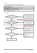
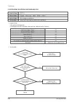
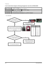
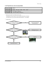
4-4-4
0
O
u
tdoor
C
o
n
d
O
u
t
se
n
sor
b
rea
k
a
w
a
y
error
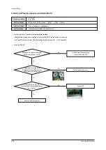
Y
es
Y
es
I
s
the
C
ond
Ou
t
sensor
and
the
sensor
ho
l
der
c
orre
c
t
ly
atta
c
hed
?
A
re
there
an
y
c
han
g
es
n
the
v
a
lu
e
o
f
the
sensor
w
hen
operatin
g
f
ro
m
stop
to
heatin
g
?
I
s
the
C
ond
Ou
t
sensor
resistan
c
e
v
a
lu
e
reasona
b
l
e
?
(
R
e
f
er
to
E
2
3
1
)
C
o
m
p
l
ete
R
e
-
insert
sensor
.
R
e
-
atta
c
h
sensor
ho
l
der
.
Y
es
1
.
Ju
d
g
m
ent
Method
1
)
No
inspe
c
tion
f
or
C
oo
l
in
g
operation
.
2
)
F
or
heatin
g
operation
(E
a
c
h
o
f
the
c
onditions
b
e
l
o
w
needs
to
b
e
satis
f
ied
f
or
m
ore
than
2
0
m
in
u
tes
.)
H
i
g
h
press
u
re
a
v
era
g
e
>
25
kg
/
c
m
²
OK
L
o
w
press
u
re
a
v
era
g
e
< 8
.
5
kg
/
c
m
²
OK
T
e
v
a
,
o
u
t
- T
air
,
in
≥
3
°C
OK
T
e
v
a
,
in
- T
air
,
in
≥
2
°C
OK
T
c
ond
,
o
u
t
- T
air
,
o
u
t
≤ 0°C
N
O
Ev
er
y
c
o
m
pressor
is
in
operation
&
indoor
u
nit
operation
and
T
her
m
o
O
n
OK
E
rror
C
ontent
Ou
tdoor
C
ond
Ou
t
sensor
b
rea
k
a
w
a
y
error
No
De
f
e
c
ti
v
e
S
ensor
:
R
ep
l
a
c
e
S
ensor
No
Bl
o
ck
ed
S
ensor
Path
:
C
han
g
e
heat
e
x
c
han
g
er
A
ss
'y
No
×(O
peration
)
ስ
(
R
eser
v
ation
)
ስ
(Bl
ast
)
ስ
(F
i
l
ter
)
×(
De
f
rost
)
∙ Ou
tdoor
C
ond
Ou
t
sensor
b
rea
k
a
w
a
y/
de
f
e
c
ti
v
e
/
re
l
e
v
ant
path
b
l
o
ck
ed
.
∙
R
e
f
er
to
the
ju
d
g
m
ent
m
ethod
b
e
l
o
w.
I
ndoor
u
nit
disp
l
a
y
Ju
d
g
m
ent
Method
C
a
u
se
o
f
pro
b
l
e
m
Ou
tdoor
u
nit
disp
l
a
y
Содержание AM160FNBFEB/EU
Страница 283: ...PCB Diagram and Parts List Samsung Electronics 5 7 5 1 4 360 cassette MAIN PCB 1 2 3 4 5 6 7 8 9 10 11 12 13 ...
Страница 295: ...PCB Diagram and Parts List Samsung Electronics 5 19 5 1 10 Duct type HSP BLDC PCB 1 2 3 4 ...
Страница 297: ...PCB Diagram and Parts List Samsung Electronics 5 21 5 1 11 Duct type Super 1 2 3 5 4 6 9 10 11 12 13 14 15 16 7 8 ...
Страница 299: ...PCB Diagram and Parts List Samsung Electronics 5 23 5 1 12 Celing type 1 2 3 4 5 6 7 19 18 9 10 11 12 17 15 14 13 8 ...
Страница 307: ...PCB Diagram and Parts List Samsung Electronics 5 31 5 1 15 Wall Mounted type A3050 MAIN 1 2 4 5 6 7 8 10 11 9 12 13 3 ...
Страница 318: ...Wiring Diagram 6 4 Samsung Electronics 6 1 4 BIG Duct This Document can not be used without Samsung s authorization ...
Страница 319: ...Wiring Diagram Samsung Electronics 6 5 6 1 5 Ceiling This Document can not be used without Samsung s authorization ...
Страница 320: ...Wiring Diagram 6 6 Samsung Electronics 6 1 6 Console This Document can not be used without Samsung s authorization ...
Страница 328: ...Wiring Diagram 6 14 Samsung Electronics 6 1 14 ERV Plus This Document can not be used without Samsung s authorization ...

