T
ro
u
b
l
eshooting
4-
5
4
S
ams
u
ng
El
ectronics
4-4-9 El
e
c
tro
n
i
c Exp
a
n
sio
n V
a
lv
e
o
p
e
n
i
ng m
a
lfunc
tio
n (
2
n
d
sta
g
e
) -
×(O
peration)
×(T
imer)
◑
(F
an)
×(F
i
l
ter)
×(
Defrost)
t
F
a
ul
t
y I
ndoor
U
nit
EEV
action.
(
Refrigerant
wi
ll l
eak
into
the
stopped
I
ndoor
U
nit.)
t
Refer
to
the
ju
dgment
method
be
l
ow.
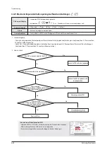
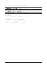
Indoor unit display
Criteria
Cause of problem
Outdoor unit display
1
.
H
ow
to
diagnose
-
D
u
ring
C
oo
l
ing
operation
,
the
temperat
u
re
of
the
in
l
et
or
o
u
t
l
et
of
stopped
H
eat
Ex
changer
is
kept
l
ower
than
0˚C
for
more
than
2
0
min
u
tes
witho
u
t
cessation.
- Hy
dro
U
nit
:
D
u
ring
the
defrost
operation
,
detection
from
stop
-
side
I
ndoor
U
nit.
(T
emperat
u
re
of
the
in
l
et
of
H
eat
Ex
changer
is
kept
l
ower
than
0˚C
for
more
than
2
0
min
u
tes
witho
u
t
cessation.)
2.
H
ow
to
check
1
st
detection
:
P
70
3
(Ou
tdoor
U
nit
disp
l
a
y
on
ly
)
2nd
detection
:
x x x (x x x : T
he
address
of
the
error
occ
u
rred
indoor
u
nit)
* H
o
w
to
t
u
r
n
o
ff
t
h
e
Hy
dro
Un
it
E151
- Hy
dro
U
nit
P
CB
k
1,
k2
switch
: A
t
the
same
time
p
u
sh
for
more
than
4
seconds.
- A
fter
reso
lv
ing
the
ca
u
se
of
the
error
,
restart
operation.
(Ex
cessi
v
e
reset
operation
,
can
ca
u
se
damage
to
the
H
eat
Ex
changer.)
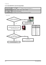
전자
팽창밸브
정상
작동
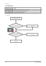
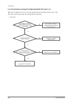
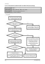
Is the EE
V
wire connected to the P
CB?
Yes
No
No
No
No
Yes
Yes
Yes
C
onnect to P
CB
and restart operation.
C
onnect the EE
V
coil properl
y
and
restart operation.
Is the EE
V
coil connected to the main bod
y
properl
y?
A
fter measuring
the coil terminal resistance, is there a disconnection or
short circuit inside the coil
?
Normal operation of EE
V
.
A
fter Resetting
the
O
utdoor Unit, does an error occur even after
running it again with the same
combination
?
Replace EE
V
coil
Содержание AM160FNBFEB/EU
Страница 283: ...PCB Diagram and Parts List Samsung Electronics 5 7 5 1 4 360 cassette MAIN PCB 1 2 3 4 5 6 7 8 9 10 11 12 13 ...
Страница 295: ...PCB Diagram and Parts List Samsung Electronics 5 19 5 1 10 Duct type HSP BLDC PCB 1 2 3 4 ...
Страница 297: ...PCB Diagram and Parts List Samsung Electronics 5 21 5 1 11 Duct type Super 1 2 3 5 4 6 9 10 11 12 13 14 15 16 7 8 ...
Страница 299: ...PCB Diagram and Parts List Samsung Electronics 5 23 5 1 12 Celing type 1 2 3 4 5 6 7 19 18 9 10 11 12 17 15 14 13 8 ...
Страница 307: ...PCB Diagram and Parts List Samsung Electronics 5 31 5 1 15 Wall Mounted type A3050 MAIN 1 2 4 5 6 7 8 10 11 9 12 13 3 ...
Страница 318: ...Wiring Diagram 6 4 Samsung Electronics 6 1 4 BIG Duct This Document can not be used without Samsung s authorization ...
Страница 319: ...Wiring Diagram Samsung Electronics 6 5 6 1 5 Ceiling This Document can not be used without Samsung s authorization ...
Страница 320: ...Wiring Diagram 6 6 Samsung Electronics 6 1 6 Console This Document can not be used without Samsung s authorization ...
Страница 328: ...Wiring Diagram 6 14 Samsung Electronics 6 1 14 ERV Plus This Document can not be used without Samsung s authorization ...

