7-4
S
a
m
s
u
n
g
El
e
c
troni
c
s
1
.
Prepare
a
re
c
har
g
ea
b
l
e
e
x
c
lu
si
v
e
re
f
ri
g
erant
c
ontainer
,
a
s
c
a
l
e
,
and
a
Mani
f
o
l
d
g
a
u
g
e
.
2
.
C
he
ck
the
a
m
o
u
nt
o
f
re
f
ri
g
erant
re
m
ainin
g
in
the
o
v
era
ll
s
y
ste
m
at
the
ti
m
e
.
3
.
C
onne
c
t
the
re
f
ri
g
erant
c
ontainer
to
the
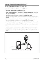
o
u
tdoor
u
nit
as
sho
w
n
in
the
f
o
ll
o
w
in
g
f
i
g
u
re
,
and
operate
on
ly
a
b
o
u
t
5
0%
o
f
the
tota
l
indoor
u
nits
in
air
c
onditionin
g
m
ode
.
4
.
C
he
ck
the
hi
g
h
press
u
re
f
ro
m
the
Mani
f
o
l
d
g
a
u
g
e
10
m
in
u
tes
a
f
ter
the
air
c
onditionin
g
b
e
g
ins
operation
.
R
ed
u
c
e
the
n
u
mb
er
o
f
indoor
u
nits
in
operation
i
f
the
hi
g
h
press
u
re
g
oes
a
b
o
v
e
3
0
kg
/
c
m
2
,
g.
to
l
o
w
er
the
hi
g
h
press
u
re
b
e
l
o
w
3
0
kg
/
c
m
2,
g.
5
.
C
he
ck
that
the
hi
g
h
press
u
re
g
oes
b
e
l
o
w
3
0
kg
/
c
m
2,
g
,
and
open
the
Mani
f
o
l
d
g
a
u
g
e
c
onne
c
ted
to
the
l
i
qu
id
pipe
,
as
w
e
ll
as
the
re
f
ri
g
erant
c
ontainer
v
a
lv
e
,
so
that
the
re
f
ri
g
erant
f
l
o
w
s
f
ro
m
the
l
i
qu
id
pipe
to
the
re
f
ri
g
erant
c
ontainer
.
6
.
C
he
ck
the
c
han
g
es
in
the
w
ei
g
ht
o
f
the
c
ontainer
u
sin
g
the
s
c
a
l
e
.
O
n
c
e
the
desired
a
m
o
u
nt
o
f
re
f
ri
g
erant
is
f
i
ll
ed
u
p
inside
the
c
ontainer
,
c
l
ose
the
v
a
lv
es
,
and
then
re
m
o
v
e
the
Mani
f
o
l
d
g
a
u
g
e
.
7
.
T
he
a
m
o
u
nt
o
f
re
f
ri
g
erant
that
c
an
b
e
c
ontained
inside
the
c
ontainer
is
a
b
o
u
t
5
0%
o
f
the
a
m
o
u
nt
o
f
re
f
ri
g
erant
inside
the
o
v
er
a
ll
s
y
ste
m
.
8
.
P
l
ease
ta
k
e
e
x
tra
c
a
u
tion
b
y
pre
c
ise
ly
deter
m
inin
g
the
a
m
o
u
nt
o
f
the
re
f
ri
g
erant
that
c
an
b
e
p
u
t
in
ea
c
h
c
ontainer
so
that
too
m
u
c
h
re
f
ri
g
erant
is
not
c
ontained
in
the
c
ontainer
.
T
he
w
ei
g
ht
m
u
st
b
e
m
eas
u
red
b
y u
sin
g
a
s
c
a
l
e
to
a
v
oid
p
u
ttin
g
m
ore
re
f
ri
g
erant
than
the
a
m
o
u
nt
ori
g
ina
lly
c
ontained
in
the
c
ontainer
.
7-
3
H
o
w
to
Pu
t
R
e
f
ri
g
era
n
t
i
n R
e
f
ri
g
era
n
t
C
o
n
tai
n
er
7-
3
-1 H
o
w
to
pu
t
re
f
ri
g
era
n
t
i
n c
o
n
tai
n
er
b
e
f
ore
pump-
do
wn
S
c
a
l
e
L
i
qu
id
Pipe
C
onne
c
tion
G
as
Pipe
C
onne
c
tion
Содержание AM160FNBFEB/EU
Страница 283: ...PCB Diagram and Parts List Samsung Electronics 5 7 5 1 4 360 cassette MAIN PCB 1 2 3 4 5 6 7 8 9 10 11 12 13 ...
Страница 295: ...PCB Diagram and Parts List Samsung Electronics 5 19 5 1 10 Duct type HSP BLDC PCB 1 2 3 4 ...
Страница 297: ...PCB Diagram and Parts List Samsung Electronics 5 21 5 1 11 Duct type Super 1 2 3 5 4 6 9 10 11 12 13 14 15 16 7 8 ...
Страница 299: ...PCB Diagram and Parts List Samsung Electronics 5 23 5 1 12 Celing type 1 2 3 4 5 6 7 19 18 9 10 11 12 17 15 14 13 8 ...
Страница 307: ...PCB Diagram and Parts List Samsung Electronics 5 31 5 1 15 Wall Mounted type A3050 MAIN 1 2 4 5 6 7 8 10 11 9 12 13 3 ...
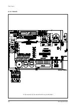
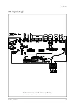
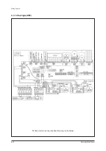
Страница 318: ...Wiring Diagram 6 4 Samsung Electronics 6 1 4 BIG Duct This Document can not be used without Samsung s authorization ...
Страница 319: ...Wiring Diagram Samsung Electronics 6 5 6 1 5 Ceiling This Document can not be used without Samsung s authorization ...
Страница 320: ...Wiring Diagram 6 6 Samsung Electronics 6 1 6 Console This Document can not be used without Samsung s authorization ...
Страница 328: ...Wiring Diagram 6 14 Samsung Electronics 6 1 14 ERV Plus This Document can not be used without Samsung s authorization ...


