4-
2
S
ams
u
ng
El
ectronics
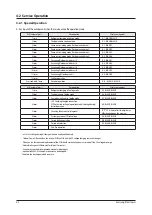
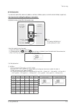
4-2 Service Operation
4-2-1 Special Operation
ـ
K
e
y
inp
u
t
of
the
o
u
tdoor
u
nit
when
the
ser
v
ice
enters
the
operation
mode.
K1 (
N
u
mber
of
press)
K
e
y
operation
Disp
l
a
y
on
segment
1
time
Refrigerant
charging
in
H
eating
mode
K, 1, BLA
N
K, BLA
N
K
2
times
T
ria
l
operation
in
H
eating
mode
K,
2
, BLA
N
K, BLA
N
K
3
times
P
u
mp
o
u
t
in
H
eating
mode
(Ou
tdoor
u
nit
address
1
)
K,
3
, BLA
N
K, 1
4
times
P
u
mp
o
u
t
in
H
eating
mode
(Ou
tdoor
u
nit
address
2)
K,
3
, BLA
N
K,
2
5
times
P
u
mp
o
u
t
in
H
eating
mode
(Ou
tdoor
u
nit
address
3)
K,
3
, BLA
N
K,
3
6
times
P
u
mp
o
u
t
in
H
eating
mode
(Ou
tdoor
u
nit
address
4
)
K,
3
, BLA
N
K, 4
7
times
V
ac
uu
mig
(Ou
tdoor
u
nit
address
1
)
K, 4, BLA
N
K, 1
8
times
V
ac
uu
mig
(Ou
tdoor
u
nit
address
2)
K, 4, BLA
N
K,
2
9
times
V
ac
uu
mig
(Ou
tdoor
u
nit
address
3)
K, 4, BLA
N
K,
3
10
times
V
ac
uu
mig
(Ou
tdoor
u
nit
address
4
)
K, 4, BLA
N
K, 4
11
times
V
ac
uu
ming
(All
o
u
tdoor
u
nits)
K, 4, BLA
N
K, A
1
2
times
E
nd
K
e
y
operation
-
Press
and
ho
l
d
1
time
Au
to
tria
l
operation
K, K, BLA
N
K, BLA
N
K
K
2
(
N
u
mber
of
press)
K
e
y
operation
Disp
l
a
y
on
segment
1
time
Refrigerant
charging
in
C
oo
l
ing
mode
K,
5
, BLA
N
K, BLA
N
K
2
times
T
ria
l
operation
in
C
oo
l
ing
mode
K, 6, BLA
N
K, BLA
N
K
3
times
P
u
mp
down
a
ll u
nits
in
C
oo
l
ing
mode
K, 7, BLA
N
K, BLA
N
K
4
times
H/
R
: C
hecking
the
pipe
connection
H/
P
: Au
tomatic
setting
of
operation
mode
(C
oo
l
ing
/H
eating)
for
trai
l
operation
K, 8, BLA
N
K, BLA
N
K
5
times
C
hecking
the
amo
u
nt
of
refrigerant
“K” “9” X X (
Disp
l
a
y
of
l
ast
two
digits
ma
y
differ
depending
on
the
progress)
6
times
Discharge
mode
of
D
C l
ink
v
o
l
tage
K, A, BLA
N
K, BLA
N
K
7
times
F
orced
defrost
operation
K, B, BLA
N
K, BLA
N
K
8
times
F
orced
oi
l
co
ll
ection
K, C, BLA
N
K, BLA
N
K
9
times
E
nd
K
e
y
operation
-
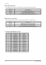
ఐ
I
n
v1 & I
n
v
2
v
o
l
tage
d
u
ring
discharge
mode
are
disp
l
a
y
ed
a
l
ternate
ly
.
ఐ͑
Ou
tdoor
Power
O
ff
e
v
en
when
the
I
n
v
erter
P
CB, F
an
P
CB
is
a
high
D
C v
o
l
tage
charging
contacts
at
danger.
ఐ͑͑
W
hen
y
o
u
r
u
n
the
repair
and
rep
l
acement
of
the
P
CB
sho
ul
d
work
after
the
power
is
t
u
rned
off
,
the
D
C v
o
l
tage
discharge.
(
Nat
u
ra
l
discharge
u
nti
l
P
l
ease
wait
for
at
l
east
1
5
min
u
tes.)
ఐ͑͑
I
f
an
error
occ
u
rs
,
the
discharge
mode
ma
y
not
work
proper
ly
.
I
n
partic
ul
ar
, E464 & E
3
64
is
power
de
v
ices
can
be
damaged.
T
herefore
,
the
discharge
mode
,
do
not
u
se.
Содержание AM160FNBFEB/EU
Страница 283: ...PCB Diagram and Parts List Samsung Electronics 5 7 5 1 4 360 cassette MAIN PCB 1 2 3 4 5 6 7 8 9 10 11 12 13 ...
Страница 295: ...PCB Diagram and Parts List Samsung Electronics 5 19 5 1 10 Duct type HSP BLDC PCB 1 2 3 4 ...
Страница 297: ...PCB Diagram and Parts List Samsung Electronics 5 21 5 1 11 Duct type Super 1 2 3 5 4 6 9 10 11 12 13 14 15 16 7 8 ...
Страница 299: ...PCB Diagram and Parts List Samsung Electronics 5 23 5 1 12 Celing type 1 2 3 4 5 6 7 19 18 9 10 11 12 17 15 14 13 8 ...
Страница 307: ...PCB Diagram and Parts List Samsung Electronics 5 31 5 1 15 Wall Mounted type A3050 MAIN 1 2 4 5 6 7 8 10 11 9 12 13 3 ...
Страница 318: ...Wiring Diagram 6 4 Samsung Electronics 6 1 4 BIG Duct This Document can not be used without Samsung s authorization ...
Страница 319: ...Wiring Diagram Samsung Electronics 6 5 6 1 5 Ceiling This Document can not be used without Samsung s authorization ...
Страница 320: ...Wiring Diagram 6 6 Samsung Electronics 6 1 6 Console This Document can not be used without Samsung s authorization ...
Страница 328: ...Wiring Diagram 6 14 Samsung Electronics 6 1 14 ERV Plus This Document can not be used without Samsung s authorization ...

