T
ro
u
b
l
eshooting
4-70
S
ams
u
ng
El
ectronics
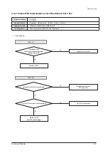
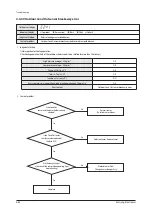
4-4-
2
6 In
ter
n
a
l C
o
mmun
i
c
atio
n
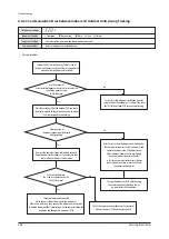
error
o
f
t
h
e
O
u
tdoor
Un
it
C-B
o
x
Ou
tdoor
u
nit
disp
l
a
y
I
ndoor
u
nit
disp
l
a
y
×(O
peration)
ስ
(
Reser
v
ation)
ስ
(Bl
ast)
×(F
i
l
ter)
×(
Defrost)
Ju
dgment
Method
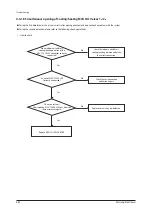
∙ C
omm
u
nication
error
between
the
C-B
o
x
P
CB
C
a
u
se
of
prob
l
em
∙ C
omm
u
nication
wire
inside
the
C-B
o
x
is
u
nconnected
∙
Main
P
CB
defecti
v
e
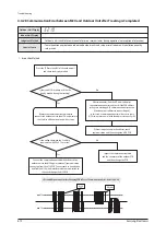
1
.
C
a
u
se
of
prob
l
em
Rep
l
ace
Main
P
CB
Restart
operation
after
connecting
the
I
n
v
erter
P
CB
2
C
N3
1(
when
the
C
omp.
app
l
ied
one
:
I
n
v
erter
P
CB1
)
connector.
(C
heck
the
3
, 4
Pin
short)
*
S
er
v
ice
after
t
u
rn
off
the
Main
Power.
No
Y
es
Did
the
C
omm
u
nication
connector
break
awa
y
from
the
P
CB?
Restart
operation
after
checking
the
I
n
v
erter
P
CB
2
C
N3
1
and
P
CB
2
C
N32
C
omm
u
nication
wire
/C
onnector.
(
3
, 4
Pin
S
hort)
*
S
er
v
ice
after
t
u
rn
off
the
Main
Power.
No
Y
es
Y
es
I
s
I
n
v
erter
P
CB1 C
N32
and
I
n
v
erter
P
CB
C
N3
1
connector
acc
u
rate
ly
connected
?
1
)
C
heck
the
I
n
v
erter
P
CB1 C
N32
, C
N
91
and
F
an
P
CB C
N
1
2
C
omm
u
nication
wire
/C
onnector.
2)
Restart
operation
after
connecting
the
Hu
b
P
CB
C
N
97
and
F
an
P
CB C
N
1
3
connector.
*
S
er
v
ice
after
t
u
rn
off
the
Main
Power.
1
)
C
heck
the
Main
P
CB :
Main
P
CB TX
circ
u
it
inspection
2)
C
heck
the
Hu
b
P
CB : Hu
b
P
CB TX
circ
u
it
inspection
*
S
er
v
ice
after
t
u
rn
off
the
Main
Power.
No
No
Y
es
I
s
I
n
v
erter
P
CB1 C
N32
and
F
an
P
CB
C
N
1
2
connector
acc
u
rate
ly
connected
?
C
onfirm
a
b
l
inking
of
F
an
P
CB L
D22
,
32
?
T
wo
C
omp.
app
l
ied
to
the
mode
l
Содержание AM160FNBFEB/EU
Страница 283: ...PCB Diagram and Parts List Samsung Electronics 5 7 5 1 4 360 cassette MAIN PCB 1 2 3 4 5 6 7 8 9 10 11 12 13 ...
Страница 295: ...PCB Diagram and Parts List Samsung Electronics 5 19 5 1 10 Duct type HSP BLDC PCB 1 2 3 4 ...
Страница 297: ...PCB Diagram and Parts List Samsung Electronics 5 21 5 1 11 Duct type Super 1 2 3 5 4 6 9 10 11 12 13 14 15 16 7 8 ...
Страница 299: ...PCB Diagram and Parts List Samsung Electronics 5 23 5 1 12 Celing type 1 2 3 4 5 6 7 19 18 9 10 11 12 17 15 14 13 8 ...
Страница 307: ...PCB Diagram and Parts List Samsung Electronics 5 31 5 1 15 Wall Mounted type A3050 MAIN 1 2 4 5 6 7 8 10 11 9 12 13 3 ...
Страница 318: ...Wiring Diagram 6 4 Samsung Electronics 6 1 4 BIG Duct This Document can not be used without Samsung s authorization ...
Страница 319: ...Wiring Diagram Samsung Electronics 6 5 6 1 5 Ceiling This Document can not be used without Samsung s authorization ...
Страница 320: ...Wiring Diagram 6 6 Samsung Electronics 6 1 6 Console This Document can not be used without Samsung s authorization ...
Страница 328: ...Wiring Diagram 6 14 Samsung Electronics 6 1 14 ERV Plus This Document can not be used without Samsung s authorization ...


