T
ro
u
b
l
eshooting
4-6
S
ams
u
ng
El
ectronics
غ
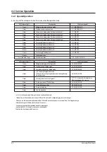
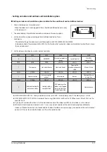
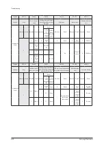
Forced defrost operation
ـ
F
orced
defrost
operation
: I
s
operation
when
F
rost
F
ormation
occ
u
rs
in
the
o
u
tdoor.
(W
hen
carried
o
u
t
the
ser
v
ice)
غ
Forced oil recovery operation
ـ
F
orced
oi
l
reco
v
er
y
operation
: O
i
l
reco
v
er
y
in
the
o
u
tdoor
u
nit
for
the
p
u
rpose
of
mo
v
ing
,
insta
ll
ation
if
necessar
y
.
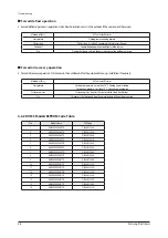
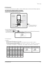
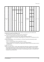
Method
of
E
ntr
y
K
2
T
act
S
witch
6
times
S
tart
pattern
H
eating
commissioning
pattern
Defrost
start
Defrost
start
: I
t
is
after
10
min
u
tes
which
S
afet
y S
tart
finishes.
Defrost
off
G
enera
l
defrost
operation
conditions
are
the
same
as.
E
tc.
Defrost
sh
u
t
down
and
stop
the
norma
l
pattern
of
the
o
u
tdoor
u
nit
stop.
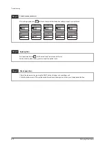
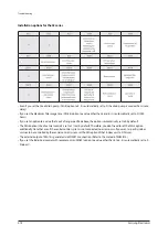
Method
of
E
ntr
y
K
2
T
act
S
witch
7
times
S
tart
pattern
Ou
tdoor
temperat
u
re
is
more
than
10°C : C
oo
l
ing
commissioning
Ou
tdoor
temperat
u
re
is
l
ess
than
10°C : H
eating
commissioning
O
i
l
reco
v
er
y
start
O
i
l
reco
v
er
y
start
: I
t
is
after
10
min
u
tes
which
S
afet
y S
tart
finishes.
E
tc.
O
i
l
reco
v
er
y
sh
u
t
down
and
stop
the
norma
l
pattern
of
the
o
u
tdoor
u
nit
stop.
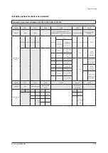
4-2-2 DVM S Models EEPROM Code Table
No.
Mode
l
Name
EE
P
C
ode
1
A
M
080FXVAGH/TK
D
B8
2
-01
35
8A
2
A
M
100FXVAGH/TK
D
B8
2
-01
35
9A
3
A
M
1
2
0FXVAGH/TK
D
B8
2
-01
3
60A
4
A
M
140FXVAGH/TK
D
B8
2
-01
3
61A
5
A
M
160FXVAGH/TK
D
B8
2
-01
3
6
2
A
6
A
M
180FXVAGH/TK
D
B8
2
-01
3
6
3
A
7
A
M2
00FXVAGH/TK
D
B8
2
-01
3
64A
8
A
M22
0FXVAGH/TK
D
B8
2
-01
3
6
5
A
9
A
M
080FXVAG
R
/TK
D
B8
2
-01
33
0A
10
A
M
100FXVAG
R
/TK
D
B8
2
-01
33
1A
11
A
M
1
2
0FXVAG
R
/TK
D
B8
2
-01
332
A
1
2
A
M
140FXVAG
R
/TK
D
B8
2
-01
333
A
1
3
A
M
160FXVAG
R
/TK
D
B8
2
-01
33
4A
14
A
M
180FXVAG
R
/TK
D
B8
2
-01
335
A
1
5
A
M2
00FXVAG
R
/TK
D
B8
2
-01
33
6A
16
A
M22
0FXVAG
R
/TK
D
B8
2
-01
33
7A
Содержание AM160FNBFEB/EU
Страница 283: ...PCB Diagram and Parts List Samsung Electronics 5 7 5 1 4 360 cassette MAIN PCB 1 2 3 4 5 6 7 8 9 10 11 12 13 ...
Страница 295: ...PCB Diagram and Parts List Samsung Electronics 5 19 5 1 10 Duct type HSP BLDC PCB 1 2 3 4 ...
Страница 297: ...PCB Diagram and Parts List Samsung Electronics 5 21 5 1 11 Duct type Super 1 2 3 5 4 6 9 10 11 12 13 14 15 16 7 8 ...
Страница 299: ...PCB Diagram and Parts List Samsung Electronics 5 23 5 1 12 Celing type 1 2 3 4 5 6 7 19 18 9 10 11 12 17 15 14 13 8 ...
Страница 307: ...PCB Diagram and Parts List Samsung Electronics 5 31 5 1 15 Wall Mounted type A3050 MAIN 1 2 4 5 6 7 8 10 11 9 12 13 3 ...
Страница 318: ...Wiring Diagram 6 4 Samsung Electronics 6 1 4 BIG Duct This Document can not be used without Samsung s authorization ...
Страница 319: ...Wiring Diagram Samsung Electronics 6 5 6 1 5 Ceiling This Document can not be used without Samsung s authorization ...
Страница 320: ...Wiring Diagram 6 6 Samsung Electronics 6 1 6 Console This Document can not be used without Samsung s authorization ...
Страница 328: ...Wiring Diagram 6 14 Samsung Electronics 6 1 14 ERV Plus This Document can not be used without Samsung s authorization ...

