LIFT MODEL VISION AS 300 Rev001
8-5
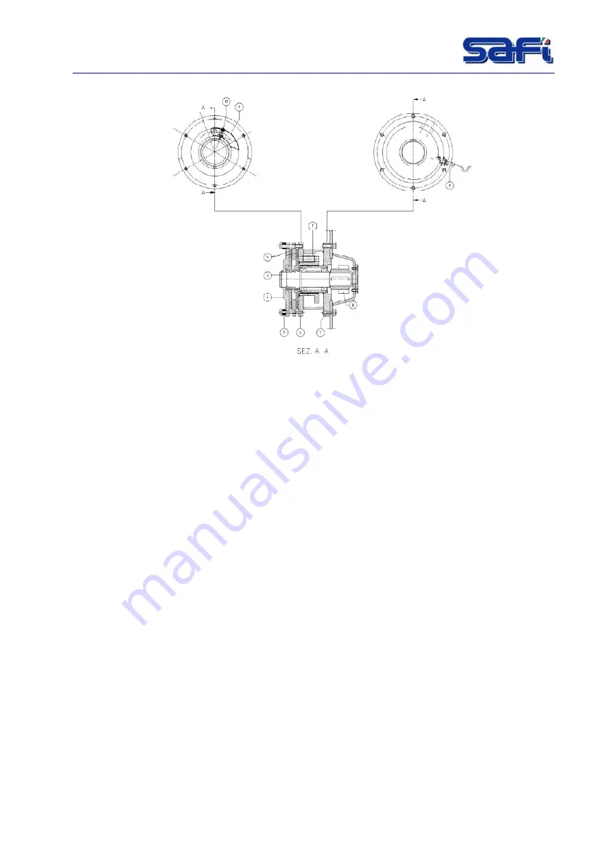
Fig. 8-1 : Parachute brake
Operating
Every motor group is equipped with a parachute which gets tripped downwards when the
machine (very exceptional case) exceeds its nominal speed: this happens only and necessarily
in the event that the motors driving parts are broken. When -during the descent- the nominal
speed is exceeded, the centrifugal mass expands (1). As a result, the support flange holdfast
(7) gets hooked and the mass holding flange (6) together with the closing up flange (4) will stop.
The pads (5), being coupled to the shaft (3) through a groove profile, keep on turning until the
compression between the mass holding flange and the closing up flange, created by the springs
(2), stops the shaft where the pinion (8) which engages the rack is splined. The stop distance is
regulated by the compression of the Belleville washers (2). The strength which contrasts the
expansion at the nominal speed of the counter-weight is generated by a spring (10) adjustable
by means of a screw.
ATTENTION:
The annual test is compulsory in order to test the efficiency of the
parachute brake and it must be required by the user to the
manufacturer or to the mandatory!
ATTENTION:
Grease the parachute brake every 3-4 months!
Содержание VISION AS 300
Страница 2: ......
Страница 4: ......
Страница 43: ...LIFT MODEL VISION AS 300 Rev001 7 4 Fig 7 1 Dimension...
Страница 68: ...LIFT MODEL VISION AS 300 Rev001 12 1 12 WIRING DIAGRAMS Fig 12 1 Wiring diagram Power supply...
Страница 69: ...LIFT MODEL VISION AS 300 Rev001 12 1 Fig 12 2 Wiring diagram Motor power supply...
Страница 70: ...LIFT MODEL VISION AS 300 Rev001 12 2 Fig 12 3 Wiring diagram Emergency circuit...
Страница 71: ...LIFT MODEL VISION AS 300 Rev001 12 3 Fig 12 4 Wiring diagram Auxiliary...
Страница 72: ...LIFT MODEL VISION AS 300 Rev001 12 4 Fig 12 5 4 Wiring diagram Auxiliary PLC logo expans...
Страница 73: ...LIFT MODEL VISION AS 300 Rev001 12 5 Fig 12 6 Auxiliary circuit...
Страница 74: ...LIFT MODEL VISION AS 300 Rev001 12 6 Fig 12 7 Wiring diagram Connectors C1 C2 C3...
Страница 75: ...LIFT MODEL VISION AS 300 Rev001 12 7 Fig 12 8 Wiring diagram Terminal box electric panel...
Страница 76: ...LIFT MODEL VISION AS 300 Rev001 12 8 Fig 12 9 Wiring diagram Cable call floor...
Страница 77: ...LIFT MODEL VISION AS 300 Rev001 12 9 Fig 12 10 Wiring diagram Floors call connection...
Страница 78: ...LIFT MODEL VISION AS 300 Rev001 12 10 Fig 12 11 Wiring diagram Box floor call connection...
Страница 79: ...LIFT MODEL VISION AS 300 Rev001 12 11 Fig 12 12 Wiring diagram Box Fencing connection...
Страница 80: ...LIFT MODEL VISION AS 300 Rev001 12 12 Fig 12 13 Wiring diagram Cable fancing call...
Страница 81: ...LIFT MODEL VISION AS 300 Rev001 12 13 Fig 12 14 Main electrical box components...
Страница 82: ...LIFT MODEL VISION AS 300 Rev001 12 14 Fig 12 15 Material list 1...
Страница 83: ...LIFT MODEL VISION AS 300 Rev001 12 15 Fig 12 16 Material list 2...


