


LIFT MODEL VISION AS 300 Rev001
5-10
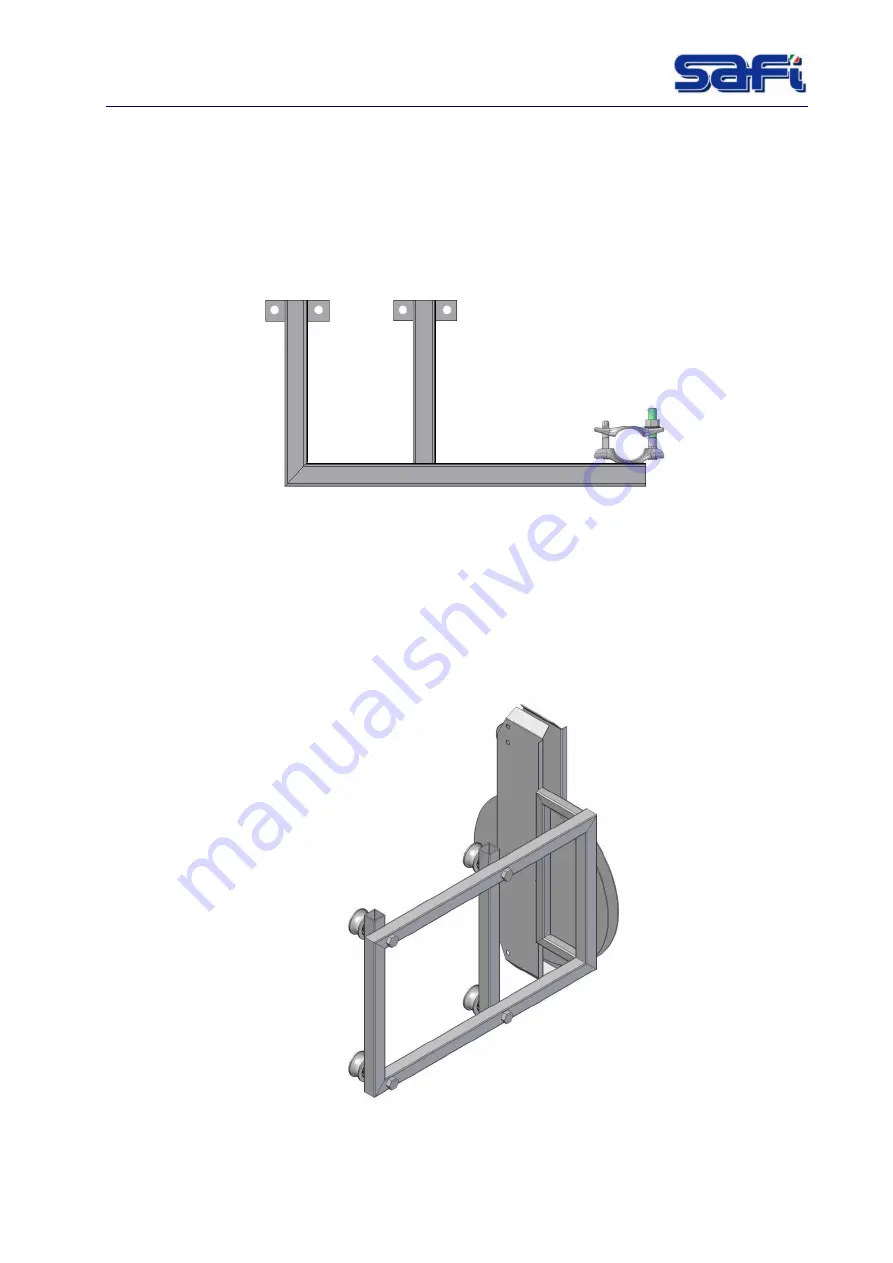
5.11
Cable-guiding arm
This is a device to keep and guide the electric cable vertical.
They are mounted vertically depending on required internal distance
Mount the cable guiding devices so that the cable-holder arm and the trolley
pre-tensioning
device
can ensure good function; check always their working order.
Fig. 5-12 : Cable guiding arm
5.12
Trolley
In order to guarantee a correct usage of the power cable, the machine is supplied with a
trolley (pre-tensioning device) installed under the cabin.
One end of the cable to the cabin and the other end to the electrical box (in the mid
height).
The trolley guides the cable through a wheel installed on a frame which is
free to move along the hoist mast.
Fig. 5-13 : Trolley pre-tensioning device
Содержание VISION AS 300
Страница 2: ......
Страница 4: ......
Страница 43: ...LIFT MODEL VISION AS 300 Rev001 7 4 Fig 7 1 Dimension...
Страница 68: ...LIFT MODEL VISION AS 300 Rev001 12 1 12 WIRING DIAGRAMS Fig 12 1 Wiring diagram Power supply...
Страница 69: ...LIFT MODEL VISION AS 300 Rev001 12 1 Fig 12 2 Wiring diagram Motor power supply...
Страница 70: ...LIFT MODEL VISION AS 300 Rev001 12 2 Fig 12 3 Wiring diagram Emergency circuit...
Страница 71: ...LIFT MODEL VISION AS 300 Rev001 12 3 Fig 12 4 Wiring diagram Auxiliary...
Страница 72: ...LIFT MODEL VISION AS 300 Rev001 12 4 Fig 12 5 4 Wiring diagram Auxiliary PLC logo expans...
Страница 73: ...LIFT MODEL VISION AS 300 Rev001 12 5 Fig 12 6 Auxiliary circuit...
Страница 74: ...LIFT MODEL VISION AS 300 Rev001 12 6 Fig 12 7 Wiring diagram Connectors C1 C2 C3...
Страница 75: ...LIFT MODEL VISION AS 300 Rev001 12 7 Fig 12 8 Wiring diagram Terminal box electric panel...
Страница 76: ...LIFT MODEL VISION AS 300 Rev001 12 8 Fig 12 9 Wiring diagram Cable call floor...
Страница 77: ...LIFT MODEL VISION AS 300 Rev001 12 9 Fig 12 10 Wiring diagram Floors call connection...
Страница 78: ...LIFT MODEL VISION AS 300 Rev001 12 10 Fig 12 11 Wiring diagram Box floor call connection...
Страница 79: ...LIFT MODEL VISION AS 300 Rev001 12 11 Fig 12 12 Wiring diagram Box Fencing connection...
Страница 80: ...LIFT MODEL VISION AS 300 Rev001 12 12 Fig 12 13 Wiring diagram Cable fancing call...
Страница 81: ...LIFT MODEL VISION AS 300 Rev001 12 13 Fig 12 14 Main electrical box components...
Страница 82: ...LIFT MODEL VISION AS 300 Rev001 12 14 Fig 12 15 Material list 1...
Страница 83: ...LIFT MODEL VISION AS 300 Rev001 12 15 Fig 12 16 Material list 2...