LIFT MODEL VISION AS 300 Rev001
7-7
56.
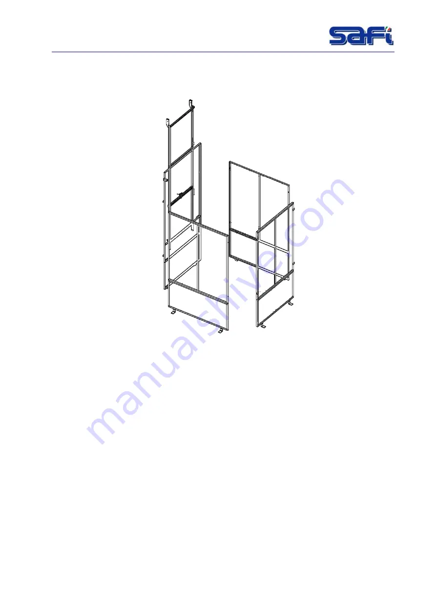
57. Mount the base fence; the connection of the various panels is effected by means of
special screws.
58.
Fig. 7-4 : Mounting – Fence
59.
7.8
Operation of the elevator car door opening and lift door
When the
cabin
is not at ground level, the fence door cannot raise as it is locked by the
mechanical door lock.
When the
cabin
is at ground level, the door disengaging slide mounted on the
cabin
door acts
on the door locking device disengaging the holdfast and allowing the fence door to open.
In such situation the weight of the fence door added to the
cabin
door's is perfectly balanced by
the counterweights system. Therefore, to open the fence door from outside just raise it by a
minimum effort.
It is likewise easy to open the
cabin
door from inside the
cabin,
as the hoisting thrust is helped
by the fence door.
When the
cabin
rises the doors must be shut completely.
While rising, the
cabin
rises too. As a result the fence door climbs. The holdfast intervention will
prevent the fence door from rising further.
When the cabin is not at ground level, the
cabin
door cannot be
opened
as it isdisconnected
from the counterweights system, it will be very heavy.
The exit of the
cabin
is divided into two parts. One half gets opened sliding vertically upwards,
the other half sliding downwards. The closing of the two parts is ensured by a mechanical door
lock.
Содержание VISION AS 300
Страница 2: ......
Страница 4: ......
Страница 43: ...LIFT MODEL VISION AS 300 Rev001 7 4 Fig 7 1 Dimension...
Страница 68: ...LIFT MODEL VISION AS 300 Rev001 12 1 12 WIRING DIAGRAMS Fig 12 1 Wiring diagram Power supply...
Страница 69: ...LIFT MODEL VISION AS 300 Rev001 12 1 Fig 12 2 Wiring diagram Motor power supply...
Страница 70: ...LIFT MODEL VISION AS 300 Rev001 12 2 Fig 12 3 Wiring diagram Emergency circuit...
Страница 71: ...LIFT MODEL VISION AS 300 Rev001 12 3 Fig 12 4 Wiring diagram Auxiliary...
Страница 72: ...LIFT MODEL VISION AS 300 Rev001 12 4 Fig 12 5 4 Wiring diagram Auxiliary PLC logo expans...
Страница 73: ...LIFT MODEL VISION AS 300 Rev001 12 5 Fig 12 6 Auxiliary circuit...
Страница 74: ...LIFT MODEL VISION AS 300 Rev001 12 6 Fig 12 7 Wiring diagram Connectors C1 C2 C3...
Страница 75: ...LIFT MODEL VISION AS 300 Rev001 12 7 Fig 12 8 Wiring diagram Terminal box electric panel...
Страница 76: ...LIFT MODEL VISION AS 300 Rev001 12 8 Fig 12 9 Wiring diagram Cable call floor...
Страница 77: ...LIFT MODEL VISION AS 300 Rev001 12 9 Fig 12 10 Wiring diagram Floors call connection...
Страница 78: ...LIFT MODEL VISION AS 300 Rev001 12 10 Fig 12 11 Wiring diagram Box floor call connection...
Страница 79: ...LIFT MODEL VISION AS 300 Rev001 12 11 Fig 12 12 Wiring diagram Box Fencing connection...
Страница 80: ...LIFT MODEL VISION AS 300 Rev001 12 12 Fig 12 13 Wiring diagram Cable fancing call...
Страница 81: ...LIFT MODEL VISION AS 300 Rev001 12 13 Fig 12 14 Main electrical box components...
Страница 82: ...LIFT MODEL VISION AS 300 Rev001 12 14 Fig 12 15 Material list 1...
Страница 83: ...LIFT MODEL VISION AS 300 Rev001 12 15 Fig 12 16 Material list 2...


