manualshive.com logo in svg
background image

17

 SL6+ v.3.30 EN

Configuration

Android

iPhone

Android

iPhone

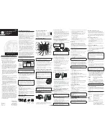
Press the SL6+ icon. To access a device it must have a programmed 

password or have been restarted within 10 minutes. Every time the 

device is powered on, the device’s bluetooth is open for 10 min-

utes, allowing you to program a password for the unit. Note: some 

devices are quicker than other to find the devices nearby. If the 

device doesn’t appear on the screen, try waiting a bit longer.

When accessing a SL6+ you can see the device information at the top.

Android

iPhone

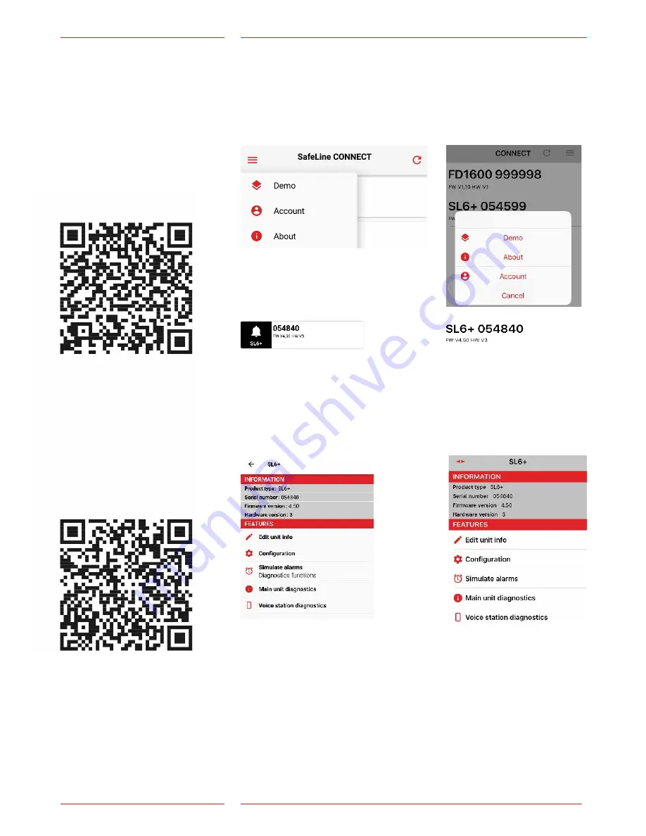
You can then select:

Edit unit info

– This is the name and phone number of the device and how the  

device is found.

Configuration:

– Here you configure all the functions for voice stations, in- and  

outputs etc.

Simulate alarms:

– Here it is possible to simulate an alarm, battery failure, callback,  

stuck button etc.

Main unit diagnostics:

– See current status of the device (for example: battery status, active 

 alarms, mains status, etc.)

Voice station diagnostics:

– Se current status of voice stations.

Configure 

with Safeline  

CONNECT

The SafeLine CONNECT app  

is used to configure and  

surveil your SafeLine devices.

Apple store, iPhone

Google play, Android

Download SafeLine CONNECT from Google Play or the Apple App 

Store. To fully use the app’s features you must register an account. 

In the upper corner you can access a menu containing account 

information, patch notes and a demo mode. To register an account: 

select account and then ”Register new account”. You will then be 

redirected to a site where you register your product key.

Содержание SL6+

Страница 1: ...afeline group com 01 2019 2019SafeLine andall the SafeLine productsand accessoriesarecopyrightedby law Compliesto EN81 28andEN81 70standards PATENT08163634 2 Lift EmergencyTelephone SL6 v 3 30EN SL6 M...

Страница 2: ...e CONNECT 17 ParametersuniqueforSafeLineCONNECT 18 ConfigurationwithPC 19 Configurationwithtelephone 20 Remoteconfigurationwithtelephone Step1 21 Remoteconfigurationwithtelephone Step2 22 On siteconfi...

Страница 3: ...arge 13 65VDC max 200mA Emergencylight Emergency lightoutput 12VDCmax500mA Emergencysignal Acousticemergencysignaloutput 12VDCmax200mA Inputs 10 30VDC 5mA opticallyisolated Antennaconnector SMA female...

Страница 4: ...ufacturer acceptsno liabilityarisingfromprintingerrors mistakesorchanges Declaration of conformity Download The declarationofconformity atourwebsite www safeline group com SafetyPrecautions Onlytraine...

Страница 5: ...etweenmainunit and stations The bus systemconsistsoffourwires twofortransfering voiceanddata and two forpowersupply Usethe adressselectorto setauniqueadressforeachstation ranging from 1 6 It is import...

Страница 6: ...indicators a Mainspower b Activealarm battery status c PSTN GSM netcallstatus 4 USBMini BPCconnection Forfirmware updateand configuration 5 RS232PCconnection For configuration 6 Screw terminal for opt...

Страница 7: ...e13 Screwconnectorterminals Emergency light Isconnectedwith Cable13 Hearingloop Isconnectedwith Cable13 RS232PCconnection Forfirmwareupdate TerminalRJ45 Input output busconnection powerand externalpic...

Страница 8: ...2 7 8 SL6 v 3 30EN Installation 1 Addressselector Fixed valuesetto 1 carunit 2 Connections 3 Pictogramoutput 4 Additionalalarm button N O 5 RS232PCconnection 6 Volumecontrol 7 Emergencylight onlyforS...

Страница 9: ...stablesurface eg wall controllercabinet usingappropriate screws Noterminationresistanceisneededattheendsofthebus To avoid GSM interference placethemainunit thestationsandthe GSMantennaatleast1 5meter...

Страница 10: ...lay 1 Common Relay 1 N C Relay 1 N O Phone line Phone line Bus 12 VDC Bus GND Bus A Bus B Battery 12 VDC Battery 0 VDC 12 VDC Input 2 configurable Input 1 configurable Emerg bell Emerg bell Emerg ligh...

Страница 11: ...ither SafeLine Pro or CONNECT N O default or N C Parameter 89 please refer to the corresponding code in the Parameter List Grey Orange Black Red Yellow Green Blue Brown Input B not in use Input A alar...

Страница 12: ...above It s possible to connect up to nine SL6 main units to the same telephone line In order to access the unit remotely it needs to be assigned a unit number Please refer to parameter 82 in the Param...

Страница 13: ...akeacallfromyourphonetoverifythattheSIMcardisactive 4 Makea calltotheSL6 afterinsertiontoensurethereisaproper connection 1111 PINcode IfthePINis setto 1111 thecodewillberandomlygeneratedbythe SafeLine...

Страница 14: ...ous red Batterytestfailure nobattery connected LED2indicates activealarm and batterycondition Flashinggreen 100 100ms Fire mode activated Flashinggreen 400 400ms Callconnectioninprogress Slowlyflashin...

Страница 15: ...llowLED GreenLED Light off Noalarmactivated TelephonelinenotOK Flashingslowly Flashing onceevery5seconds Telephone line notOK Flashingonceevery5seconds UnitisOK Flashingquickly Flashing twiceeveryseco...

Страница 16: ...ne lineisconnectedoraGSMnetis available LED3isflashinggreen every5seconds 6 Refer to chapter Trouble shooting main unit Example foundallvoice stations exceptfornumber3 Startup procedure Connect230VAC...

Страница 17: ...nfigure all the functions for voice stations in and outputs etc Simulate alarms Here it is possible to simulate an alarm battery failure callback stuck button etc Main unit diagnostics See current sta...

Страница 18: ...built inmagnetbutton In and outputs Relay1 2 Emergencybuttoncheck During emergencybuttoncheck therelayisactivatedfor 3seconds waitingfor emergencybuttonsignal Ifmainunitdoes notreceive message a stuck...

Страница 19: ...officepriortotheinstallationoron siteafterinstallation The configurationsoftwareSafeLineProcanbe downloaded fromwww safeline group com Theconfigurationcable isprovided by SafeLine Remoteconfigurationw...

Страница 20: ...onpage6 Enterconfigurationcodesonthehandsetkeypad Remote configuration with telephone For remote configuration you can use any PSTN tone dial phone Dial the phone number of the SL6 Enter the function...

Страница 21: ...eentered Press unitnumber 1 9 1 Dialthephonenumberof theunit 2 Ifthereisonlyoneunit inthesystem proceedto step4 Iftherearemultiple unitsconnectedinparallel proceedtostep3 3 After2ringsthefirstSL6 unit...

Страница 22: ...sword 2shortbeeps enteringconfig mode 2shortbeeps Continue configure Quitconfiguration Invalidpassword onelongtone 2short beeps Invalidinput one longtone Lastcodehas tobe re entered Calldisconnectedor...

Страница 23: ...ne Dial toenter configurationmode 2short beeps enteringconfig mode Continueconfigure 2shortbeeps Invalidinput onelongtone Lastcodehas tobereentered Calldisconnected orend ofconfiguration SL6 willresta...

Страница 24: ...number 2ndphonenumber Calltype1stnumber Calltype2st number Alarmbutton delay Endconfiguration Example2 SLCC SafeLine CallCentre and3daytest Startconfiguration Enter P100IDcode Set test alarmtype Setnu...

Страница 25: ...aytime canbesetbyaddingasterisks between leadingnumberoftheswitchboardand telephonenumberforthealarmcallreceiver Eachasterisk isequaltooneseconddelay Example 1 11 0 1234567 Example 2 11 deletesthephon...

Страница 26: ...adeaftertheconfigurationis terminated Daysbetweentests 27 Numberofdaysbetweentestalarms 00 99 days Alwaystwodigits Max3daysaccordingtoEN81 28 00 Notestalarms Testalarmprotocol 31 0 P100 3 CPC 4 Caller...

Страница 27: ...ethecallpress To playtherecordedmessage pressthe desiredparameterfollowed by Forexample 61 inodertoplaythe messagefromthebusunit 0 Disablerecorded message 1 Enablesrecordedmessage Recordalarm messagef...

Страница 28: ...ult Ring tone timeout 72 Number of ring signals before dialling the next number default 08 External inputs Function 73 The first number selects the input i e Input 1 or Input 2 The second number selec...

Страница 29: ...ough the unit is programmed as automatic by pressing No ascending tones will be heard For repeating the Alarm messages to operator press 1 in all in out going calls 3 Swiss Mode Alarm operator mode On...

Страница 30: ...rlater thefollowingparametersare used 0 Alarmstatusoutputs default relay 1 1 Battery failure default relay 2 2 Pictogram Relay1 yellow relay2 green 3 ActivatewithDTMF8 9 relay1 DTMF8 relay2 DTMF9 4 Ma...

Страница 31: ...sanalarmeventafterconfigurationistermi nated 1 Emergencycall 2 Testalarm 3 Batteryfailure 4 Microphone speakerfailure 5 Receiptonvoicecall 6 Maintenance 7 Mainunit powerfailure 8 Stuckbuttonalarm GSM...

Страница 32: ...et Relay willbe activated whensettimereached Emergency callfailure Relay willbe activated whentheemergencycallfailedafter12 attempts EmergencyCallFail Systemfailure Relaywillbeactivated whenpower 230V...

Страница 33: ...lt Relayactivatesonceeveryday Ifsomethingiswrongwithbutton analarmissenttothe alarmreceiver IfDBcollective faultis programmedonanoutput thisis released Resets whenemergencybuttoninputischanged 3 Callr...

Страница 34: ...arunit Intercombetweenmachine roomandcar pit car top Mainstationtovoice station Press1 6onthe handset tocallrespectivevoicestation Voice stationtomainstation Pressthebuttononthe voicestationbrieflytoc...

Страница 35: ...utton again Alarmoperator madeconnection Calling1st phonenumber Calling2nd phonenumber Calling3rd phone number Calling4th phonenumber Wait1minute Linemissing orbusy Emergencyalarm activated Dialtone E...

Страница 36: ...k disabled PSTNinterface Flashing Red 400 400ms no line Slowly flashinggreen 200 4600ms lineOK Flashing green 400 400ms connectingcall Continuous green callconnected Fallback disabled GSMinterface Con...

Страница 37: ...larmdrop offfailsthroughtheprioritizedinterface theunitalsotriesthe secondaryinterface Ifdrop offfailsthrough any of theinterfaces e g noresponse busyline noP100starttone acknowledgement and Fallbacki...

Страница 38: ...eakerofthemainunitduringtheactive time Press the resetbuttontostopthesirensound Avoicemessagespecifically forFiremodeisplayed Refertothe Distressmessage sectionofthe ParameterList table When Firemodei...

Страница 39: ...rmed Thebatterytesttakesabout20minutes Ifthebatteryislow thetestwillbecancelled Whenusingtherelay LED 2andthebatteryalarmrelaywillbeactivated Relayscanbe activated forbatteryalarmbyusingparameter 88 p...

Страница 40: ...calltothecar press 1 Alternatively press 0 andwaitfordialtone thendialan externalcall Ifthesound transmissionisOK inbothdirections checkifyour emergencyoperatorsupportsthe chosenalarmtype Ifnoprotocol...

Страница 41: ...tle external interference Doamicrophonetest ThepictogramLEDsareflashing quicklyandsimultaneously The address switch is set to an invalid number 0 7 8 9 Valid numbers are 1 6 Theaddressswitchsetting ha...

Страница 42: ...oneof thesesolutions apply installaseparatecableforthetelephoneline Microphonecheck Call intotheSL6 and press thefollowingnumbersonthecaller s phone 1 Press 7 toactivate the car smicrophone 2 Press ac...

Страница 43: ...N 12015 2014 EMC Emission Electromagnetic compatibility EN 12016 2013 EMC Lifts Immunity Electromagnetic compatibility EN 62368 1 2014 AC 2015 LVD Information Technology Equipment EN 50581 2012 RoHS T...

Страница 44: ...0 60 03 sld safeline eu SafeLine Norway Solbr veien 49 1383 Asker Norway Tel 47 94 14 14 49 post safeline no SafeLine Denmark Erhvervsvej 19 2600 Glostrup Denmark Tel 45 44 91 32 72 info dk safeline s...

Отзывы: