


MRL100 / 942 / 699Plus
A1- Instruction Manual
Digital load / weight measuring system
S2Tech srl
Via Imperia, 28 Milano – ITALY
Tel: +39 02 8910142 Fax: + 39 02 89124848
www.s2tech.it
Version : UK 2r7 dated 25/06/15
Page: 2/4
Notice:
The information in this manual is subject to change without notice.S2Tech shall not be liable for technical or editorial errors or omissions contained herein, nor for incidental or consequential damages resulting from the furnishing, performance, or use of this material. This manual contains information protected by
copyright. No part of this manual may be photocopied, or reproduced in any form, or translated without prior written consent from S2Tech.
Z:\Manuali\LM MRL100_942_699A1\Traduzioni Maggio 2015\LM MRL_942_699A1 V2r7 UK .docx
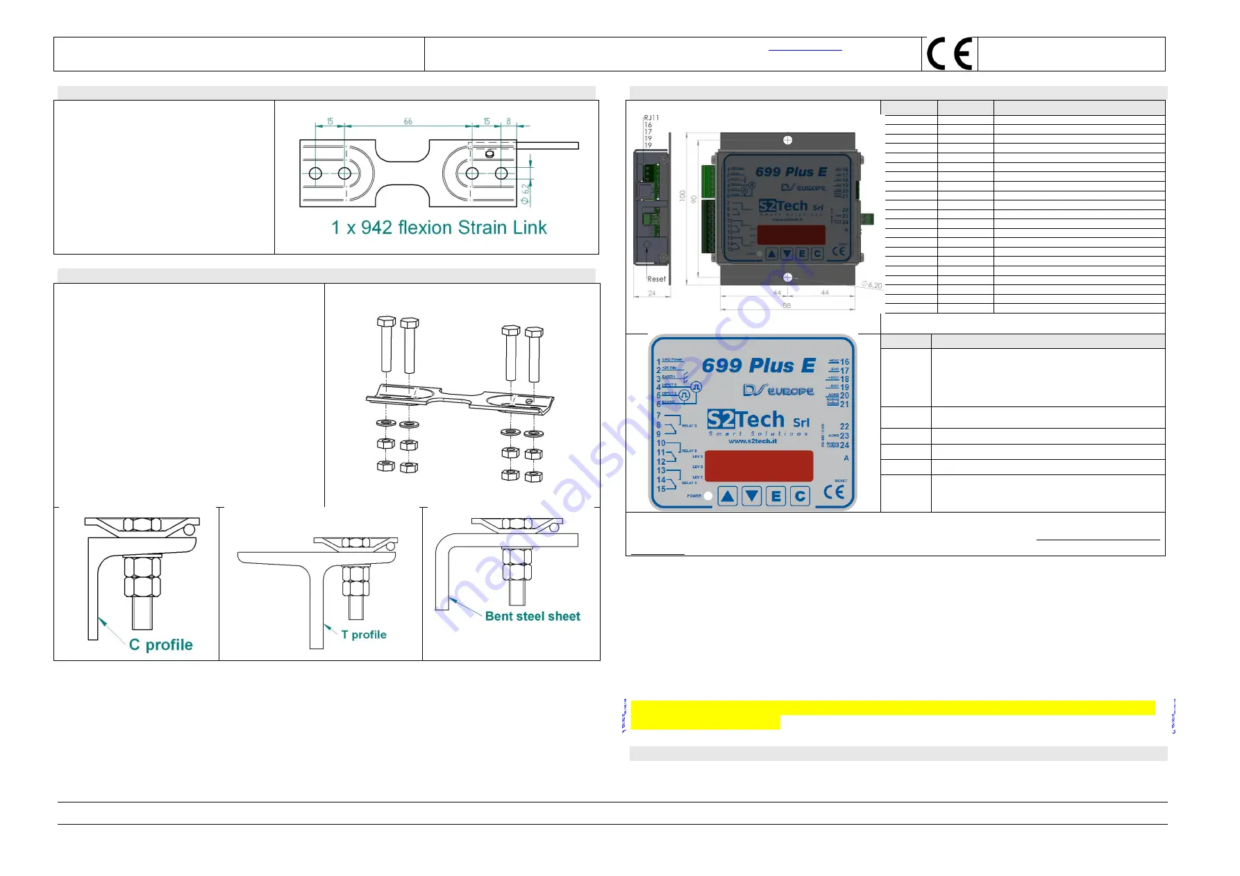
C) 942
Strain Link
System composition
Supplied material:
N° 1
942 Strain Link
transducer
N° 4 Screws, type M 6x30 8.8 DIN 933
N° 4 Flat Washers M 6, type UNI 6592
N° 8 Fixing M6 nuts
D) How to install 942 Strain Link transducer on lift’s structure
1)
Strain link 942 and 699 electronics are to be
fixed and installed on the lift frame.
2)
Strain link 942 is to be fixed on a flat and clean
surface, without rust, paint grease or oil.
3)
Tighten the 4 screws to fix strain link 942 and
use only flat washers.
4)
Set electrical connections accordingly to
connection chart of this manual.
5)
Ground to earth 699 electronics and respect all
relevant safety and electrical regulations.
6)
Feed power supply to STRAINSENTRY and
wait 15 minutes before calibrating.
E) Digital indicator and load limiter model 699 F
Terminal board
connection
Type
Meaning
1
Screw Terminal
GND (DC POWER SUPPLY )
2
Screw Terminal
+ 24 V (DC POWER SUPPLY)
3
Screw Terminal
EARTH connection
4
Screw Terminal
CONTACT I/O 2 (
option
)
5
Screw Terminal
CONTACT I/O 1 (Chain compensation -
option
)
6
Screw Terminal
I/O CONTACT's common reference (
option
)
7
Screw Terminal
Relay 3 - Normally Open contact (
option
)
8
Screw Terminal
Relay 3 - Normally Closed contact (
option
)
9
Screw Terminal
Relay 3 Common contact (
option
)
10
Screw Terminal
Relay 2 - Normally Open contact
11
Screw Terminal
Relay 2 - Normally Closed contact
12
Screw Terminal
Relay 2 Common contact
13
Screw Terminal
Relay 1 - Normally Open contact
14
Screw Terminal
Relay 1 - Normally Closed contact
15
Screw Terminal
Relay 1 Common contact
16
Screw Terminal
+ power supply to transducer
17
Screw Terminal
- power supply to transducer
18
Screw Terminal
+ signal form transducer
19
Screw Terminal
- signal from transducer
23
Screw Terminal
AGND (Analog output)
24
Screw Terminal
Analog Output
NOTE:
on serial connections (optional, RS485 or CAN), use solely twisted pair
shielded cables, with shield connected to earth at both ends
.
Code
Meaning
ER.10
OVER RANGE - Verify the mechanical fixing of 942 strain
link. Try to substitute the 942 and re-calibrate.
ER.22
High load sensitivity. Fix 942 to a more rigid part of the lift
frame or substitute it.
ER.23
HI value is too low (in engineering units).
ER.24
Load specimen is too low. Increase load.
ER.30
Damaged A/D converter. Substitute 699 Electronics.
ER.70
Electrical connection problem. Check connections and that
cable has not been damaged.
Ground to earth the 699 electronics and respect all the relevant safety and electrical regulations.
Once performed all the needed electrical connections feed power supply and wait 15 minutes, before
calibrating.
Measurement changes are displayed in tens of the used engineering units.
At 699 power on, or after a reset
, display will show in sequence
699F
, the firmware release version (i.e.
1.05
) and:
UCAL
, if unit is not calibrated or if default data are loaded
MCAL
, if it has been calibrated using the
MANU
procedure
Supplied material:
N° 1 699 Digital conditioner complete of mating connectors (removable screw terminal), with reference to
the ordered configuration
N° 2 Fixing screws, type M4 x 12 UNI 7687
N° 2 Nuts, type M4
Perform calibration of the installed
MultiRope MRL100
load measuring system when lift’s car is at
the lowest floor of the plant.
CE DECLARATION
699 digital conditioner complies with the requirements of the following norms:
EN 61326-1(1997) + A1(1998) + A2(2001) + A3(2003); EN 61000-6-2(2001); EN 61000-3-2(2000) + A2(2005);EN 61000-3-3(1995) + A1(2001); EN 61000-
4-2 (1995) + A1(1998) +A2(2001); EN 61000-4-3(2002) + A1(2002); EN 61000-4-4(1995) + A1(2001) + A2(2001); EN 61000-4-5(1995) + A1(2001);
EN61000-4-6(1996) + A1(2001); EN 61000-4-8(1993)+A1(2001); EN 61000-4-11(2004)


