


108
TX11 June 2011
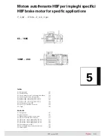
5. Motore autofrenante HBF per impieghi
specifici
5. HBF brake motor for specific applications
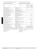
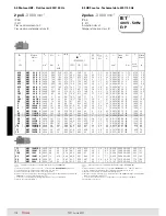
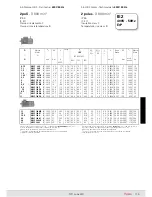
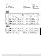
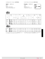
Dimensioni principali di accoppiamento delle forme costruttive
con flangia
Main mating dimensions of the mounting positions with flange
Carcassa
di lega leggera pressofusa; forma costruttiva IM B3 con
piedi riportati e, per grand. 90 ... 200, montabili su
tre lati.
Scudo lato comando
(
o flangia
)
e
lato opposto comando
di ghi sa
o di lega leggera (ved. tabella).
Scudi e flange con
attacchi di ser-
raggio «in appoggio»
e montati
sulla carcassa con accoppiamento
«
stretto
».
Cuscinetti volventi a sfere
(ved.
tabella sottoriportata) lubrificati «a
vita» in assenza di inquinamento
dall’esterno; molla di precarico.
Albero motore
di acciaio 39 NiCr-
Mo3 bonificato o C45 secondo la
grandezza,
bloccato assialmente
sullo scudo posteriore. Estremità
d’albero cilindriche con linguetta
forma A (arrotondata) e foro filet-
tato in testa (ved. tabella dove: d
= foro filettato in testa; bxhxl =
dimensioni linguetta).
Foro posteriore filettato
per
estrazione in applicazioni con ridut-
tore, di serie grand. 63 ... 160S.
Housing
in pressure diecast light alloy; mounting position IM B3
with inserted feet which, for sizes 90 ... 200, can be mounted on
three
sides
.
Drive
(
or flange
)
end
and
non-
drive end endshield
in cast iron
or light alloy (see table).
«Supported» tightening attach-
ments
of endshields and flanges
fitted on housing with «
tight
»
coupling.
Ball bearings
(see table below)
lubricated «for life» assuming
pollu tion-free surroundings; pre-
load spring.
Driving shaft:
in through-harde-
ned steel 39 NiCrMo3 or C45
depending on size,
axially faste-
ned
on rear endshield. Cylin-
drical shaft ends with A-shape
(rounded) key and tapped butt-
end hole (see table where: d =
tapped butt-end hole; bxhxl =
key dimensions).
Rear threaded
hole
for dismounting in applica-
tions with gear reducer, standard
for sizes 63 ... 160S.
Forma
costruttiva
Mounting
position
Estremità d’albero - Shaft end Ø D x E
Flangia - Flange Ø P
Grandezza motore – Motor size
IM
63
71
80
90
100, 112
132
160
180
200
11 × 23
140
14 × 30
160
19 × 40
200
24 × 50
200
28 × 60
250
38 × 80
300
42 × 110
350
48 × 110
350
55 × 110
400
9 × 20
120
11 × 23
140
14 × 30
160
19 × 40
200
24 × 50
200
28 × 60
250
38 × 80
300
3)
−
48 × 110
350
−
−
−
−
19 × 40
200
1)
24 × 50
200
2)
−
−
−
11 × 23
120
14 × 30
140
−
28 × 60
200
38 × 80
250
−
−
−
19 × 40
160
−
11 × 23
120
14 × 30
140
19 × 40
160
−
−
−
−
−
−
−
−
−
19 × 40
160
1)
−
−
−
−
11 × 23
90
14 × 30
105
19 × 40
120
24 × 50
140
28 × 60
160
38 × 80
200
−
−
−
−
11 × 23
90
14 × 30
105
−
−
−
−
−
−
LL = lega leggera G = ghisa
1) Di ghisa per IM B14 e IM B5 derivate.
2) Di ghisa per IM B5.
3) Flangia di frenatura di lega leggera con
inserto di acciaio nella pista di frenatura.
LL = light alloy G = cast iron
1) In cast iron for IM B14 and IM B5
derivatives.
2) In cast iron for IM B5.
3) Brake flange in light alloy with steel
insert in braking track.
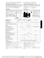
Grand. motore
Motor size
Cuscinetti e materiali scudi
Bearings and endshields material
lato comando
lato opposto
drive end
non drive end
63
LL
6202 2Z
6202 2RS
LL
71
LL
6203 2Z
6203 2RS
LL
80
LL
6204 2Z
6204 2RS
LL
90
LL
6205 2Z
6205 2RS
LL
100
LL
6206 2Z
6206 2RS
LL
112
LL
63062Z
6306 2RS
LL
132
LL
1)
6308 2Z
6308 2Z
LL
3)
160S
G
6309 2Z
6308 2Z
LL
3)
160M ... 180M
LL
2)
6310 ZC3
6309 2ZC3
G
180L
G
6310 ZC3
6310 2ZC3
G
200
G
6312 ZC3
6310 2ZC3
G
1) Forma costruttiva non disponibile per motore 112.
2) Forma costruttiva non disponibile per motore 132MA ... MC.
3) Forma costruttiva non disponibile per motore 160S.
1) Mounting position not available for motor 112.
2) Mounting position not available for motor 132MA ... MC.
3) Mounting position not available for motor 160S.
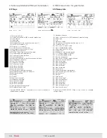
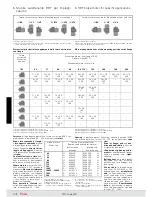
1) Forma costruttiva a richiesta.
2) Il motore può funzionare anche nelle forme costruttive IM B6, IM B7 e IM B8; in targa
rimane indicata la forma costruttiva IM B3.
1) Mounting position on request.
2) Motor can also operate in the mounting positions IM B6, IM B7 and IM B8; the name
plate shows the IM B3 mounting position.
IM
B3
2)
IM
V5
IM
V6
IM
B5
IM
V1
IM
V3
IM
B14
IM
V18
IM
V19
Forme costruttive con flangia - Mounting positions with flange
Forme costruttive con piedi - Mounting positions with feet
Содержание TX11 Series
Страница 2: ......
Страница 27: ...27 TX11 June 2011 Pagina lasciata intenzionalmente bianca This page is intentionally left blank...
Страница 35: ...35 TX11 June 2011 Pagina lasciata intenzionalmente bianca This page is intentionally left blank...
Страница 67: ...67 TX11 June 2011 Pagina lasciata intenzionalmente bianca This page is intentionally left blank...
Страница 77: ...77 TX11 June 2011 Pagina lasciata intenzionalmente bianca This page is intentionally left blank...
Страница 111: ...111 TX11 June 2011 Pagina lasciata intenzionalmente bianca This page is intentionally left blank...
Страница 121: ...121 TX11 June 2011 Pagina lasciata intenzionalmente bianca This page is intentionally left blank...
Страница 153: ...153 TX11 June 2011 Pagina lasciata intenzionalmente bianca This page is intentionally left blank...
Страница 163: ...163 TX11 June 2011 Pagina lasciata intenzionalmente bianca This page is intentionally left blank...
Страница 202: ...202 TX11 June 2011 Pagina lasciata intenzionalmente bianca This page is intentionally left blank...
Страница 203: ...203 TX11 June 2011...