Robotiq FT-150/300 Sensor
Instruction Manual
Robotiq inc. © 2016
7
Figure 1.2 represents the various force and torques that the FT Sensor can measure. Reference frame is centered
on the Sensor as shown above and visual inscriptions are also represented on it.
For both Sensors, the Z axis passes through the center of the thru hole with positive direction in the tool
direction.
For both Sensors, the X axis traces a symmetric line centered on the connector,
The FT 150 positive direction points towards the connector,
The FT-300 positive direction points the opposite way; away from the connector,
For both Sensors, the Y axis uses the right hand thumb rule according to X-Z.
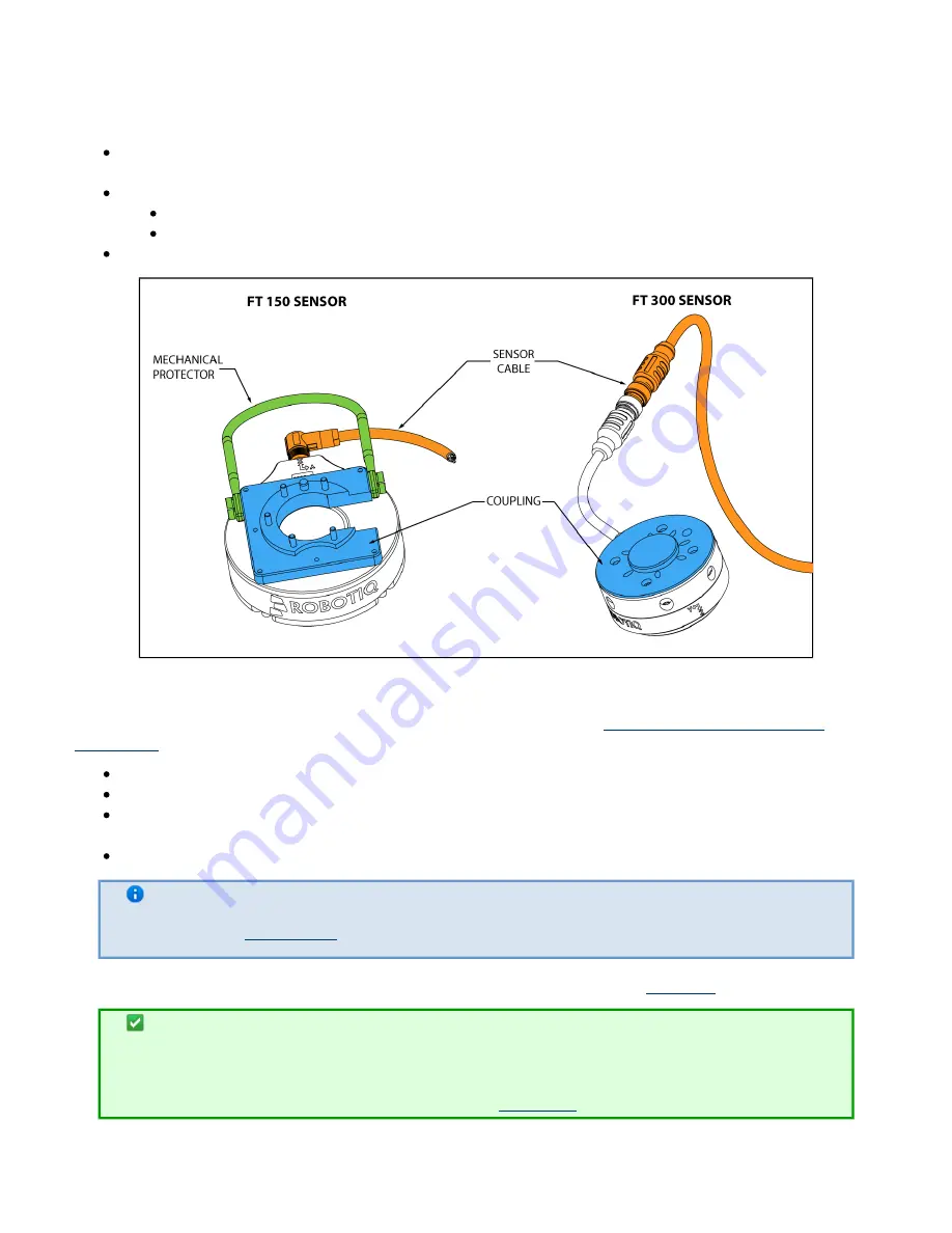
Figure 1.3 : FT Sensor options.
Figure 1.3 above represents various options available. They can be found in
Section 7. Spare Parts, Kits and
.
Couplings are meant to install the FT Sensor on various robot models, see available models.
Sensor Cable is used for power and communications with the FT Sensor and is available in different lengths.
Mechanical Protector is meant to protect the cable connector from collisions that can occur when operating
the robot (especially useful when in teach mode) (
).
only for the FT 300
Tool Plate is not shown, but might be required when certain end-of-arm tools are mounted on the FT Sensor.
Info
See Section
for details on the installation of various options.
Various software packages are provided (identical for both version) and detailed in
of this manual.
Tip
It is important to understand that the FT Sensor can be used either as a Modbus RTU slave or as
a streaming device. When use as a slave unit you will send status requests (read function) to get
the force & moment values, while when in data stream mode the Sensor will continuously stream
data without responding to a master request, see


