background image

118

Upgrade and Maintenance Guide


Upgrading SteelHead xx50 Appliances

Installing Licenses and Activating Specifications

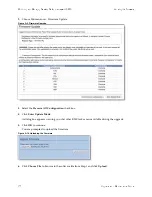
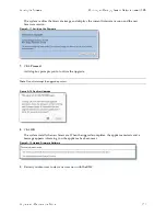
When the upgrade is complete, the appliance is transformed into the new model. The model number 
appears on the appliance banner in the upper-right corner of the screen. The appliance retains its 
original serial number. 

Note: 

After upgrading a model, desired admission control overrides must be reapplied relative to the default admission 

control values of the new model.

Содержание SteelCentral NetExpress 470

Страница 1: ...Upgrade and Maintenance Guide SteelHead CX xx70 xx55 SteelHead DX SteelHead EX xx60 SteelHead Interceptor SteelCentral xx70 SteelFusion Core May 2016 ...

Страница 2: ...registered trademarks of VMware Inc in the United States and in other countries This product includes Windows Azure Linux Agent developed by the Microsoft Corporation http www microsoft com Copyright 2012 Microsoft Corporation This product includes software developed by the University of California Berkeley and its contributors EMC and Comtech AHA Corporation This product is derived from the RSA D...

Страница 3: ...iances 13 Installing the Chassis Cover on 1U and 2U Appliances 15 Removing and Installing the Air Duct 15 Removing and Installing the Air Duct for 1U Appliances 16 Removing and Installing the Air Duct for 2U Appliances 17 Replacing Disk Drives 19 Replacing Disk Drives in 1U Appliances with 3 5 inch Drives 19 Replacing Disk Drives in 2U Appliances with 2 5 inch Drives 23 Replacing Disk Drives in 2U...

Страница 4: ...nd 2U Appliances 54 Replacing Memory Modules 55 Replacing Memory Modules in Desktop Appliances 55 Replacing Memory Modules in 1U Appliances 57 Replacing Memory Modules in 2U Appliances 59 Replacing Fans 64 Determining Fan Status 64 Replacing Fans in 1U Appliances 64 Replacing Fans in 2U Appliances 66 Chapter 3 Replacing SteelHead xx50 Components 69 Required Tools 69 Replacing Disk Drives 70 Replac...

Страница 5: ...32 GB 109 Upgrading to 64 GB 109 Chapter 5 Upgrading SteelHead xx50 Appliances 111 Overview 111 Platform Requirements 112 Upgrade Kit Hardware Contents 112 Hardware Requirements 113 Upgrading a Model Basic Steps 113 Installing Licenses and Activating Specifications 114 Model Upgrades Using the CLI 114 Model Upgrades Using the Management Console 116 Appendix A Monitoring and Managing Desktop CX App...

Страница 6: ...Up the BMC for Initial Access 134 Setting Up BMC on SteelHead and SteelFusion Core 3500 134 Setting Up BMC on NetProfiler 134 Setting Up BMC on NetShark 134 Logging In to the BMC 135 Viewing System Information 137 Viewing Server Health 137 Configuring the BMC 138 Remotely Controlling the Appliance 139 Changing the BMC Administrator Password 139 ...

Страница 7: ...250 and CSH 550 For detailed information about replacing components in the SteelHead EX560 or EX760 appliances see the Series EX560 and EX760 Systems Owner s Manual For information about SteelFusion Edge appliances see SteelFusion Edge Hardware Installation and Maintenance Guide The CX255 CX570 CX770 SMC9000 and SCC1000 appliances do not contain field replaceable components This guide only describ...

Страница 8: ...c components on system hardware Safety Guidelines Follow the safety precautions outlined in the Safety and Compliance Guide when installing and setting up your equipment Caution Failure to follow these safety guidelines can result in injury or damage to the equipment Mishandling of the equipment voids all warranties Read and follow safety guidelines and installation instructions carefully Conventi...

Страница 9: ...ion of the release notes go to the Software and Documentation section of the Riverbed Support site at https support riverbed com Examine the release notes before you begin the installation and configuration process Contacting Riverbed This section describes how to contact departments within Riverbed Technical support If you have problems installing using or replacing Riverbed products contact Rive...

Страница 10: ...10 Upgrade and Maintenance Guide Preface Contacting Riverbed ...

Страница 11: ...e 29 Replacing Memory Modules on page 30 Replacing Fans on page 34 Appliances Included in This Chapter This chapter describes how to replace components in the following appliances 1U xx70 appliances including SteelHead CX3070 SteelCentral NetExpress 470 SteelCentral NetProfiler 4270 DB UI DP SteelCentral Flow Gateway 2270 and SteelCentral NetShark 2170 2U xx70 appliances including SteelHead CX5070...

Страница 12: ...o handling equipment Use the magnetic Phillips screwdriver enclosed with your shipment to remove screws in the appliance The magnetic screwdriver ensures screws are not lost in the appliance Removing and Installing the Bezel The following procedure describes how to remove and install the front bezel on 1U and 2U xx70 appliances To remove the bezel 1 If locked unlock the bezel 2 Remove the left end...

Страница 13: ...iances Removing and Installing the Chassis Cover You need to remove the top cover to add or replace components inside the appliance This section describes how to work with the chassis cover on xx70 appliances The appliance must be operated with the appliance cover in place to ensure proper cooling Removing the Chassis Cover on 1U and 2U Appliances This section describes how to remove the chassis c...

Страница 14: ...rceptor9600 andSteelFusionCore3500Components Removingand Installing the Chassis Cover 2 Remove the four screws letter A Figure 1 3 Removing the 1U Appliance Cover Figure 1 4 Removing the 2U Appliance Cover 3 Slide the cover back and lift upward letter B ...

Страница 15: ...p cover on the appliance and slide it toward the front of chassis until the recessed front edge fits smoothly under the chassis edge and the locking pins letter A are fully engaged Figure 1 5 Installing the Appliance Cover 2 Install the three screws at the front and then install the screw at the back letter B Removing and Installing the Air Duct The appliances in this chapter require an air duct f...

Страница 16: ...eelFusionCore3500Components RemovingandInstallingtheAirDuct Removing and Installing the Air Duct for 1U Appliances Follow these instructions to remove and install the air duct for the 1U appliances To remove the air duct Lift straight up Figure 1 6 Removing the Air Duct ...

Страница 17: ... duct with the alignment pins on the chassis and lower the air duct into place Figure 1 7 Installing the Air Duct Removing and Installing the Air Duct for 2U Appliances Follow these instructions to remove and install the air duct for the 2U appliances To remove the air duct 1 For SteelHead CX SteelHead Interceptor 9600 and SteelFusion Core 3500 unplug the cables on the SSD boot drive Figure 1 8 Un...

Страница 18: ...two latches on the air duct letter A in Figure 1 9 3 Rotate the front edge of the air duct up to disengage the two tabs from the fan bulkhead letter B Figure 1 9 Removing the Air Duct To install the air duct 1 Lower back edge of the air duct to engage the two tabs on the fan bulkhead letter A 2 Carefully push in the two latches on the air duct letter B ...

Страница 19: ...rives in 1U Appliances with 3 5 inch Drives on page 19 Replacing Disk Drives in 2U Appliances with 2 5 inch Drives on page 23 Replacing Disk Drives in 2U Appliances with 3 5 inch Drives on page 25 Note If you need to replace an appliance you cannot move the disks to preserve your data Each disk is encoded with machine level information and moving disks is not supported Replacing Disk Drives in 1U ...

Страница 20: ...ove the bezel See Removing and Installing the Bezel on page 12 2 Identify the faulty disk drive The Web interface identifies the faulty disk drive On a SteelHead the Alarm Status page in the Management Console identifies the faulty drive The disk drive LED is orange for failed drives The drives are numbered in ascending order from left to right that is 0 1 2 3 SteelHead CX3070 HDDs can be in slots...

Страница 21: ...elease button and pull the drive handle toward you Figure 1 12 Removing the Disk Drive 4 Slide the faulty disk drive out of the slot 5 Remove the four screws securing the drive from the carrier and remove the failed drive Figure 1 13 Removing the Drive from the Carrier 6 Insert the new drive in the carrier and secure using the four screws ...

Страница 22: ... the chassis The disk drive LED lights blue when connected Figure 1 15 Inserting the Disk Drive 9 Press in the disk drive handle to close The new disk drive runs through a self test automatically The disk drive automatically begins proper operation with the other disk drives You do not need to set up or configure the new disk drive Note When replacing drive 2 or 3 on a NetShark 2170 Packet Storage...

Страница 23: ...ace disk drives you must wear a grounded ESD antistatic strap to protect the hardware against electrostatic discharge Make sure that the strap makes skin contact prior to handling equipment Caution Use caution when you remove or replace components they can become hot to the touch To replace a 2 5 inch disk drive in the 2U appliances 1 Remove the bezel See Removing and Installing the Bezel on page ...

Страница 24: ...andle toward you to release the disk drive Figure 1 17 Releasing the Disk Drive 4 Slide the faulty disk drive out of the slot Figure 1 18 Remove the Disk Drive 5 Remove the four screws securing the drive from the carrier and remove the failed drive Figure 1 19 Removing the Drive from the Carrier 6 Insert the new drive in the carrier and secure using the four screws ...

Страница 25: ... Press in the disk drive handle to close Figure 1 21 Inserting the Disk Drive The new disk drive runs through a self test automatically The disk drive automatically begins proper operation with the other disk drives You do not need to set up or configure the new disk drive Replacing Disk Drives in 2U Appliances with 3 5 inch Drives 2U SteelFusion Core 3500 SteelCentral NetProfiler 2270 4270 EX and...

Страница 26: ...become hot to the touch To replace a disk drive in 2U appliances with 3 5 inch drives 1 Remove the bezel See Removing and Installing the Bezel on page 12 2 Identify the faulty disk drive The Web interface displays an alarm that identifies the faulty disk drive The disk drive LED is orange for failed drives SteelFusion Core 3500 has 1TB HDD drives in slots 0 to 3 and 80GB SSDs in slots 4 and 5 NetS...

Страница 27: ...and pull the drive handle toward you to release the disk drive Figure 1 23 Releasing the Disk Drive 4 Slide the faulty disk drive out of the slot 5 Remove the four screws securing the drive from the carrier and remove the failed drive Figure 1 24 Removing the Drive From the Carrier 6 Insert the new drive in the carrier and secure using the four screws ...

Страница 28: ...es the backplane connector Figure 1 25 Inserting the Drive in the Carrier 7 Open the new disk drive handle by pressing the orange release button 8 Slide in the new disk drive until it mates with the back connectors in the chassis The disk drive LED lights blue when connected Figure 1 26 Inserting the Disk Drive 9 Press in the disk drive handle to close ...

Страница 29: ...on Replacing Power Supply Units This section describes how to replace a power supply in 1U and 2U appliances These appliances are equipped with replaceable hot swappable power supply units Caution Use caution when replacing the power supply units they can become hot to the touch To replace power supply units in 1U and 2U appliances 1 Locate the defective power supply unit and remove the power cord...

Страница 30: ...eplacement part for the AC power supplies in 2U appliances To install the DC power supply 1 Remove the AC power supply and insert the DC power supply 2 Attach the O ring terminal adapter to the DC power supply 3 Loosen the three screws on the adapter 4 Connect the positive negative and ground wires to the marked location 5 Tighten the screws around the wires Replacing Memory Modules This section d...

Страница 31: ...e the memory modules in the 1U appliances 1 Power down the appliance 2 Remove the chassis cover See Removing and Installing the Chassis Cover on page 13 3 Remove the air duct See Removing and Installing the Air Duct for 1U Appliances on page 16 4 Press the ejector tabs on the memory slots down and outward and gently pull the memory module out of the slot 5 Replace the memory module with an approve...

Страница 32: ...only one direction Figure 1 30 Inserting the Memory Modules into the Connector Slot and Securing 7 Press down on the memory module with your thumbs while pulling up on the ejectors with your index fingers to lock the module into the slot 8 Ensure that all ejector tabs are in the upright locked position 9 Replace the chassis cover 10 Replace the power cords and peripherals 11 Power on the appliance...

Страница 33: ...ce memory modules in the 2U appliances 1 Power down the appliance 2 Remove the chassis cover See Removing and Installing the Chassis Cover on page 13 3 Remove the air duct See Removing and Installing the Air Duct for 2U Appliances on page 17 4 Press the ejector tabs on the memory slots down and outward and gently pull the memory module out of the slot 5 Replace the memory module with an approved m...

Страница 34: ...e chassis cover 10 Replace the power cords and peripherals 11 Power on the appliance Replacing Fans This section describes how to identify fan status and replace fans in the 1U and 2U appliances The section includes the following procedures Determining Fan Status on page 34 Replacing Fans in 1U Appliances on page 35 Replacing Fans in 2U Appliances on page 38 You must power down appliances prior to...

Страница 35: ...ng on your appliance Note Fan status is not available on NetShark Replacing Fans in 1U Appliances This section describes how to replace fans in the 1U appliances These appliances are equipped with four fans The fans are not hot swappable you must power down the appliance before replacing the fans Note You must use approved fans To order fans contact Riverbed Support at https support riverbed com T...

Страница 36: ...lFusionCore3500Components Replacing Fans The 1U appliance has four fans in slots 2 3 4 and 5 Figure 1 33 1U Fan Numbers 3 Unplug the fan cable from the cable jack on the motherboard and remove the faulty fan from the dock Figure 1 34 Fan Cable Jacks and Removing Fan Unit ...

Страница 37: ...o the dock and plug the cables of the replacement fan unit into the cable jack Figure 1 35 Replacing a Fan 5 Replace the chassis cover Note If the RiOS IPMI alarm triggers when you open the chassis cover enter the clear hardware error log command in the CLI to clear the alarm For details see the Riverbed Command Line Interface Reference Manual ...

Страница 38: ... five dual unit hot swappable fans at the front of the chassis Important You must use approved fans To order fans contact Riverbed Support at https support riverbed com To replace the fans in the 2U appliances 1 Remove the chassis cover See To install the chassis cover on 1U and 2U appliances on page 15 2 Identify the faulty fan The appliance has five fans An LED on the fan indicates a failure Fig...

Страница 39: ...aight up to remove it Figure 1 37 Removing the Fan in 2U Appliances 4 Insert the replacement fan 5 Replace the chassis cover Note If the IPMI alarm triggers when you open the chassis cover enter the clear hardware error log command in the CLI to clear the alarm For details see the Riverbed Command Line Interface Reference Manual ...

Страница 40: ...40 Upgrade and Maintenance Guide Replacingxx70 Interceptor9600 andSteelFusionCore3500Components Replacing Fans ...

Страница 41: ...Appliances Included in This Chapter This chapter describes how to replace hardware components in the following CX DX EX and SteelFusion appliances Desktop appliances including CX255 CX555 CX755 CX570 CX770 SMC9000 and SSC1000 1U appliances including CX1555 and EX1160 For detailed information about replacing components in the EX560 or EX760 appliances see the Series EX560 and EX760 Systems Owner s ...

Страница 42: ...erbed com An antistatic strap When you replace components you must wear a grounded ESD antistatic strap to protect the hardware against electrostatic discharge Make sure that the strap makes skin contact prior to handling equipment Use the magnetic Phillips screwdriver enclosed with your shipment to remove screws in the appliance The magnetic screwdriver ensures screws are not lost in the applianc...

Страница 43: ...xx55 xx60 and SteelFusion Core 2000 Appliances Figure 2 2 Opening the Bezel on 2U xx55 xx60 DX and SteelFusion Core 3000 Appliances Removing the Chassis Cover This section describes how to remove the chassis cover on x55 xx60 and SteelFusion Core appliances It includes the following procedures Removing the Chassis Cover on the Desktop Appliances on page 44 including the CX555 and CX755 appliances ...

Страница 44: ...ee Removing Disk Drives in Desktop Appliances on page 47 To remove the chassis cover on desktop appliances 1 With the included screwdriver remove the two locking screws on the back of the chassis cover Figure 2 3 Removing the Locking Screws 2 Position your thumbs on the top of the appliance and slide the cover back from the chassis Removing the Chassis Cover on 1U Appliances This section describes...

Страница 45: ...5 Removing the Chassis Cover Removing the Chassis Cover on 2U Appliances This section describes how to remove the chassis covers for the CX5055 CX7055 DX8000 EX1260 EX1360 SteelFusion Core 2000 and SteelFusion Core 3000 appliances To remove the chassis cover on 2U appliances 1 Loosen the two locking screws on the back of the chassis Figure 2 6 Unscrewing the Locking Screws 2 Remove the third locki...

Страница 46: ...bes how to remove and replace disk drives in the CX EX and SteelFusion Core appliances This section includes the following procedures Removing Disk Drives in Desktop Appliances on page 47 Replacing Disk Drives in 1U Appliances on page 49 Replacing Disk Drives in 2U Appliances on page 50 Replacing Disk Drives in 2U Appliances on page 52 Note If you need to replace an appliance you cannot move the d...

Страница 47: ...e electric shock Caution Use caution when you remove or replace components they can become hot to the touch To replace the disk drive 1 Power down the appliance 2 Unplug the power cord from the AC circuit 3 If necessary remove the appliance from its mounting rack 4 Remove the locking screws on the cover of the chassis There is one locking screw located at the rear and two on each side Figure 2 8 R...

Страница 48: ...emove the disk drive in the casing from the appliance and place the casing on an antistatic surface 9 Remove the disk drive from the casing by removing the four screws and washers holding the disk drive casing to the chassis Figure 2 10 Removing the Casing Caution Use caution when removing the screws and washers do not drop them into the appliance 10 Reinsert the empty disk drive casing back in th...

Страница 49: ...SD antistatic strap to protect the hardware against electrostatic discharge Make sure that the strap makes skin contact prior to handling equipment Caution Use caution when you remove or replace components they can become hot to the touch To replace the disk drive in 1U appliances 1 Open the bezel See Opening the Bezel on page 42 2 Identify the faulty disk drive The Alarm Status page in the Manage...

Страница 50: ...e disk drive automatically begins proper operation with the other disk drives You do not need to set up or configure the new disk drive Note It takes approximately 3 to 4 hours depending on the system load to rebuild a new disk drive When the disk drive has finished rebuilding the system sends an email to the administrator user Replacing Disk Drives in 2U Appliances The 2U CX5055 CX7055 DX8000 EX1...

Страница 51: ... identifies the faulty disk drive The disk drive LED is orange for failed drives The drives are numbered in ascending order from left to right that is starting with 0 on the left and ending with 23 on the right For the CX5055 and CX7055 appliances disks 0 and 1 are HDDs and disks 2 to 23 are SSDs For DX8000 appliances disks 0 and 1 are HDDs DX appliances do not contain SSDs For the EX1360 applianc...

Страница 52: ...ly The disk drive automatically begins proper operation with the other disk drives You do not need to set up or configure the new disk drive Replacing Disk Drives in 2U Appliances The 2U EX1260 and SteelFusion Core 2000 appliances are equipped with replaceable hot swappable disk drives You must use approved disk drives To order disk drives contact Riverbed Support at https support riverbed com Not...

Страница 53: ... slot number This command ensures the RAID system removes the disk partitions before the drive is removed from the slot For details see the Riverbed Command Line Interface Reference Manual 4 Press the orange release button and pull the drive handle toward you to release the disk drive Figure 2 16 Releasing the Disk Drive 5 Slide the faulty disk drive out of the slot Make sure you remove the correc...

Страница 54: ...lacing Power Supply Units in 1U and 2U Appliances This section describes how to replace a power supply in 1U CX1555 and EX1160 and 2U CX5055 CX7055 DX8000 EX1260 EX1360 SteelFusion Core 2000 and SteelFusion Core 3000 appliances These appliances are equipped with replaceable hot swappable power supply units Caution Use gloves when replacing the power supply units they can become hot to the touch To...

Страница 55: ... Replacing Memory Modules in Desktop Appliances on page 55 Replacing Memory Modules in 1U Appliances on page 57 Replacing Memory Modules in 2U Appliances on page 59 Replacing Memory Modules in Desktop Appliances This section describes how to replace memory modules in desktop CX555 and CX755 appliances Note You must use approved memory modules Contact Riverbed Support at https support riverbed com ...

Страница 56: ...d memory module 6 Align the memory module edge connector with the slot alignment keys and insert it into the slot The module slot has two alignment keys that allow you to install the module in only one direction Figure 2 19 Inserting and Securing the Memory Module in the DIMM Slot 7 Press down on the memory module with your thumbs while pulling up on the ejectors with your index fingers to lock th...

Страница 57: ...hen adding new memory to the 1U xx55 and xx60 appliances add the memory in the black slots first Once the black slots are full populate the blue slots Make sure the memory is equally distributed on both sides To replace the memory modules in the 1U CX1555 and EX1160 appliances 1 Power down the appliance 2 Remove the chassis cover See To remove the chassis cover on 1U appliances on page 44 3 To acc...

Страница 58: ...sure straight out of the appliance using the attached strap Figure 2 22 Removing PCIe Enclosure 5 Remove the two screws securing the cooling shroud Figure 2 23 Removing Cooling Shroud Screws 6 Lift the cooling shroud straight up and out of the appliance Caution Lift the shroud straight up to avoid damaging any components of the appliance ...

Страница 59: ...e edge connector with the slot alignment keys and insert it into the slot The module slot has two alignment keys that allow you to install the module in only one direction Figure 2 25 Inserting the Memory Modules into the Connector Slot and Securing 10 Press down on the memory module with your thumbs while pulling up on the ejectors with your index fingers to lock the module into the slot 11 Ensur...

Страница 60: ...elFusion Core Appliances When adding new memory to the 2U appliances add the memory in the black slots first Once the black slots are full populate the blue slots Make sure the memory is equally distributed on both sides All memory slots for DX8000 appliances are populated To replace memory modules in the 2U xx55 xx60 DX and SteelFusion Core appliances 1 Power down the appliance 2 Remove the chass...

Страница 61: ...Ie enclosure remove the two locking screws on the top of the enclosure and the two locking screws on the rear panel Figure 2 27 Removing PCIe Enclosures 4 To remove the right and left PCIe enclosure from the chassis place your fingers in the enclosure holes and lift straight up Figure 2 28 Removing the PCIe Enclosures from the Chassis ...

Страница 62: ...ule slots Figure 2 29 Removing Cooling Shroud Caution Be careful not to damage any surrounding components when removing and installing the cooling shroud Lift the shroud straight up to avoid damaging any components of the appliance 6 Press the ejector tabs on the memory module slot down and outward and gently pull the memory module out of the slot Figure 2 30 Accessing the Memory Modules ...

Страница 63: ...ry modules Contact Riverbed Support at https support riverbed com to obtain the correct memory modules 9 Align the memory module edge connector with the slot alignment keys and insert it into the slot The module slot has two alignment keys that allow you to install the module in only one direction Figure 2 32 Inserting the Memory Modules into the Connector Slot and Securing 10 Press down on the me...

Страница 64: ...e fan status 1 Connect to the CLI For details see the Riverbed Command Line Interface Reference Manual 2 At the system prompt enter the show stats fan command amnesiac show stats fan FanId RPM Min RPM Status 0 4963 1080 ok 1 4963 1080 ok 2 4821 1080 ok 3 4963 1080 ok 4 4963 1080 ok 5 4821 1080 ok The output and number of fans vary depending on your appliance Replacing Fans in 1U Appliances This se...

Страница 65: ... Cable Jacks and Removing Fan Unit 4 Seat the fan unit on the metal peg on the floor of the chassis 5 Plug the cables of the replacement fan unit into the cable jacks 6 Replace the chassis cover Note If the RiOS IPMI alarm triggers when you open the chassis cover run the clear hardware error log command in the CLI to clear the alarm For details see the Riverbed Command Line Interface Reference Man...

Страница 66: ...ore 3000 appliances These appliances are equipped with four dual unit hot swappable fans at the front of the chassis Note You must use approved fans To order fans contact Riverbed Support at https support riverbed com To replace the fans in the 2U appliances 1 Remove the chassis cover See To remove the chassis cover on 2U appliances on page 45 2 Identify the faulty fan The appliance has four fan u...

Страница 67: ...l the fan up from the chassis Figure 2 35 Removing the Fan in 2U Appliances 4 Plug the replacement fan into the chassis 5 Replace the chassis cover Note If the IPMI alarm triggers when you open the chassis cover enter the clear hardware error log command in the CLI to clear the alarm For details see the Riverbed Command Line Interface Reference Manual ...

Страница 68: ...68 Upgrade and Maintenance Guide Replacing CX xx55 EX xx60 DX and SteelFusion Core Components Replacing Fans ...

Страница 69: ...ved components will result in boot failure To order components contact Riverbed Support at https support riverbed com Required Tools You need the following tools and equipment to replace appliance components You must use approved components for the appliance to function properly Installation of unapproved components will result in boot failure To order components contact Riverbed Support at https ...

Страница 70: ...Appliances SteelHead 150 250 and 550 appliances are equipped with a replaceable disk drive The disk drive is not hot swappable you must first turn off the system and remove the power cord before you replace the disk drives You must use approved disk drives To order disk drives contact your sales representative Caution SteelHead 150 250 and 550 disk drives are not hot swappable You must turn off th...

Страница 71: ... and washers holding the disk drive casing to the chassis Caution Use the magnetic screw driver that ships with the disk drive to remove the screws Use caution when removing the screws and washers do not drop them into the appliance Figure 3 2 Removing Disk Drive Screws 7 Remove the old disk drive with casing from the appliance 8 Insert the new disk drive with casing in the same position and secur...

Страница 72: ...t the data store For detailed information about the impact of upgrading your system on the data store and RSP see Platform Requirements on page 112 You must use approved disk drives To order disk drives contact your sales representative Note When you replace disk drives you must wear a grounded ESD antistatic strap to protect the hardware against electrostatic discharge Make sure that the strap ma...

Страница 73: ...e Alarm Status page in the Management Console identifies the faulty disk drive The drives are numbered in ascending order from left to right that is 0 1 2 3 On Interceptor 9350 appliances the bottom LED light indicates which drive to remove Figure 3 4 Disk Drive Numbers 3 Press the orange release button to the left and pull the drive handle toward you to release the disk drive 4 Slide the faulty d...

Страница 74: ... disk drive It takes approximately 3 to 4 hours depending on the system load to rebuild a new disk drive The administrator user receives email when the disk drive has finished rebuilding Replacing Power Supply Units This section describes how to add or replace power supply units for the xx50 appliances This section includes the following procedures Replacing Power Supply Units in Interceptor 9350 ...

Страница 75: ... until it mates with the back connectors in the chassis When the power supply unit is pushed all the way in the button clicks to the right 4 Plug the AC power cord into the new power supply unit Replacing Memory This section describes how to replace memory in the xx50 appliances DIMM Slot Locations Memory modules and slot locations vary according to the motherboard in your appliance Before you beg...

Страница 76: ...iagram shows the memory module slot locations for Interceptor 9350 appliances Figure 3 8 Memory Module Slots in Interceptor 9350 Appliances Replacing Memory Modules in SteelHead 150 250 and 550 Appliances This section describes how to replace memory modules in a SteelHead 150 250 and 550 appliance Before you begin work with Riverbed Support at https support riverbed com to determine the type of me...

Страница 77: ... makes skin contact prior to handling equipment For details see Electrostatic Discharge Guidelines on page 8 To replace the memory modules 1 Power down the system 2 Disconnect the appliance from the electrical outlet and peripherals 3 Remove the two locking screws on the back of the chassis Figure 3 9 Removing the Locking Screws 4 Position your thumbs on the top of the appliance and slide the cove...

Страница 78: ...h the approved memory module 8 Align the memory module edge connector with the slot alignment keys and insert it into the slot The module slot has two alignment keys that allow you to install the module in only one direction Figure 3 11 Inserting and Securing the Memory Module in the DIMM Slot 9 Press down on the memory module with your thumbs while pulling up on the ejectors with your index finge...

Страница 79: ...static Discharge Guidelines on page 8 To replace the memory modules 1 Power down the system 2 Disconnect the appliance from the electrical outlet and peripherals 3 Carefully lift the cover away from the appliance 4 Press the ejector tabs on the memory slots down and outward and gently pull the memory module out of the slot Figure 3 12 Accessing the Memory Modules 5 Remove the existing memory modul...

Страница 80: ...s and slot locations vary according to the motherboard in your appliance Contact Riverbed Support at https support riverbed com to determine the type of memory and slot location for the motherboard in your appliance Note When you replace memory modules you must wear a grounded ESD antistatic strap to protect the hardware against electrostatic discharge Make sure that the strap makes skin contact p...

Страница 81: ...ocking screw at the back of the chassis and pull the motherboard handle downward and slide the motherboard out 1 to 2 inches from the chassis to release the cooling shroud Lift the cooling shroud straight up and out of the appliance Caution Be careful not to damage any surrounding components when removing and installing the cooling shroud Lift the shroud straight up to avoid damaging any component...

Страница 82: ...a module of a different size causes the system to fail You must use approved memory modules Contact Riverbed Support at https support riverbed com to obtain the correct memory modules 4 Align the memory module edge connector with the slot alignment keys and insert it into the slot The module slot has two alignment keys that allow you to install the module in only one direction Figure 3 18 Insertin...

Страница 83: ...PM Min RPM Status 0 4963 1080 ok 1 4963 1080 ok 2 4821 1080 ok 3 4963 1080 ok 4 4963 1080 ok 5 4821 1080 ok The output and number of fans will vary depending on your appliance Replacing Fans in the Interceptor 9350 Appliances This section describes how to replace fans in the Interceptor 9350 These appliances are equipped with four hot swappable fans at the front of the chassis and two hot swappabl...

Страница 84: ... 19 Interceptor 9350 Fan Layout with Fan ID Numbers To replace the front fans 1 To open the bezel press the buttons on each side of the bezel and pull toward you The bezel remains attached to the appliance on hinges Figure 3 20 Opening the Appliance Bezel 5 Fan 5 6 Fan 6 Fan ID Physical Label ...

Страница 85: ... on top of the cover and slide the cover forward and then lift up and away from the chassis Figure 3 21 Removing the Front Appliance Cover 3 Identify the faulty fan 4 Pull the fan release lever upwards and pull the fan up from the chassis Figure 3 22 Releasing the Fan 5 Plug the replacement fan into the chassis 6 Replace the chassis front cover ...

Страница 86: ... while the system is running To clear this alarm run the clear hardware error log command in the CLI For details see the Riverbed Command Line Interface Reference Manual To replace the rear fans 1 To remove the rear appliance cover loosen the two locking screws on the back of the appliance Figure 3 23 Loosening the Locking Screws 2 Slide the rear cover backward several inches and then lift up and ...

Страница 87: ...r log command in the CLI For details see the Riverbed Command Line Interface Reference Manual Replacing the Motherboard in SteelHead 7050 Appliances For the SteelHead 7050 appliance you can replace the motherboard Work with Riverbed Support to complete these steps Note A video showing these instructions is on the Riverbed Support Site https support riverbed com kb multimedia htm To replace a mothe...

Страница 88: ...etwork Interface Card Installation Guide for details 12 Move the SDR acceleration card to the new motherboard Use the same procedure as you did with the network cards 13 Insert the new motherboard into the chassis Carefully align it inside the chassis and slide it into place 14 For the last inch move the handle into the upright position and secure it with the locking screw 15 Replace the back cove...

Страница 89: ...nce the appliance reboots enter the show licenses command and ensure that the licenses are valid 22 Verify the MAC addresses of the primary and AUX interfaces The primary and AUX interfaces should have new MAC addresses The MAC addresses of lan0_0 wan0_0 lan0_1 and wan0_1 remain the same ...

Страница 90: ...90 Upgrade and Maintenance Guide Replacing SteelHead xx50 Components Replacing Fans ...

Страница 91: ...s using the Riverbed command line interface CLI or the SteelHead Management Console Model upgrades always preserve the configuration of the appliance In some cases model upgrades require the installation of additional disk drives and memory modules Upgrades that require the installation of additional hardware do not preserve the data store Model Upgrades and Platform Requirements The following tab...

Страница 92: ...Hardware Kit RiOS v8 0 3 v8 5 Clears RiOS data store and log files None Yes CX770L CX770M License only RiOS v8 0 6 v8 5 3 v8 6 1 None None No CX770L CX770H License only RiOS v8 0 6 v8 5 3 v8 6 1 None None No CX770M CX770H License only RiOS v8 0 6 v8 5 3 v8 6 1 None None No CX1555L CX1555M License only RiOS v6 5 4 v7 0 1 None None No CX1555L CX1555H License and Hardware Kit RiOS v8 0 3 v8 5 Clears ...

Страница 93: ...nd Hardware Kit EX 3 5 Clears RiOS data store and log files If SteelFusion is enabled it clears the blockstore Local VSP data is not cleared None Yes EX1160M EX1160H License only EX 1 0 2 5 3 None None No EX1160M EX1160VH License and Hardware Kit EX 3 5 Clears RiOS data store and log files If SteelFusion is enabled it clears the blockstore Local VSP data is not cleared None Yes EX1160H EX1160VH Li...

Страница 94: ...is enabled it clears the blockstore Local VSP data is not cleared None Yes EX1260H EX1260VH License and Hardware Kit EX 3 5 Clears RiOS data store and log files If SteelFusion is enabled it clear the blockstore Local VSP data is not cleared None Yes EX1260G EX1260L License only EX 1 0 2 5 3 None None Yes EX1260G EX1260M License only EX 1 0 2 5 3 None None Yes EX1260G EX1260H License only EX 1 0 2 ...

Страница 95: ...he installation of hardware The hardware required for your model upgrade is contained in the Upgrade Kit shipped to you The following table lists the Upgrade Kit part numbers and hardware contents for model upgrades requiring additional hardware GC2000L GC2000H License only SteelFusion 1 0 None None No GC2000L GC2000VH License only SteelFusion 1 0 None None No GC2000M GC2000H License only SteelFus...

Страница 96: ...a model upgrade specification 3 Activate the specification Activate the model upgrade specification in the CLI or the Management Console For detailed information see Installing Licenses and Activating Specifications on page 97 4 Reboot the system if needed The system notifies you if a reboot is necessary 5 Restart the service To perform a license and hardware kit upgrade 1 Install the model upgrad...

Страница 97: ...d click Remove Core For details see the SteelHead Management Console User s Guide 4 Install the required hardware For detailed information see Installing Hardware for Model Upgrades on page 101 5 Power on the appliance The system reformats the hard drives and completes the upgrade Installing Licenses and Activating Specifications The following sections describe how to install model upgrade license...

Страница 98: ...amnesiac config write memory 7 View licenses installed on the appliance enter the show licenses command amnesiac config show licenses LIC EXAMPLE EX760H 0000 0000 0 000X 0XX0 Index 6 Feature MSPECEX760H Valid yes Active yes 8 View the available model upgrade specification enter the show hardware spec command amnesiac config show hardware spec Spec Description EX760L BW Limit 10000 Kb s Connection ...

Страница 99: ... Restart the optimization service for model upgrades that do not require a reboot enter the restart command amnesiac config restart Terminating optimization service Relaunching optimization service Note After upgrading a model you need to reapply admission control overrides relative to the default admission control values of the new model Model Upgrades Using the Management Console This section de...

Страница 100: ...he Management Console 2 Click Add a New License to display the text box to add a new license 3 Copy and paste the license key into the text box 4 Click Add to add the license 5 Click Save to save your settings permanently To activate a model upgrade specification using the Management Console 1 Choose Configure Maintenance Services to display the Services page 2 Under Optimization Service click Sto...

Страница 101: ...el upgrade does not require the installation of additional hardware click the Restart icon to restart the optimization service When the upgrade is complete the appliance is transformed into the new model The model number appears on the appliance banner in the upper right corner of the screen The appliance retains its original serial number Note After upgrading a model you need to reapply admission...

Страница 102: ...ection describes how to install memory modules and replacement disk drives for CX755L and CX755M to CX755H upgrades For the disk drive upgrade you replace the hard drive casing that contains two HDDs with a new casing that contains one SSD and one HDD Note When you install or replace memory modules you must wear a grounded ESD strap For details see Electrostatic Discharge Guidelines on page 8 To u...

Страница 103: ...e system does not function properly Figure 4 3 Adding Memory Modules for CX755 Upgrades 5 Align the memory module edge connector with the slot alignment keys and insert it into the slot The module slot has two alignment keys that allow you to install the module in only one direction Figure 4 4 Inserting and Securing the Memory Module in the DIMM Slot 6 Ensure that all ejector tabs are in the uprig...

Страница 104: ...e disk drive casing upward and out of the chassis Figure 4 5 Removing the Disk Drive Casing from Chassis 9 Insert the new disk drive with casing in the same position and secure the casing to the chassis with the three screws 10 Replace the system cover making sure the tabs of the cover are under the front frame 11 Plug the power cord into the AC circuit 12 Power on the system The system automatica...

Страница 105: ...he bezel See Opening the Bezel on page 42 3 Identify the hard disk drives to replace The drives are numbered in ascending order from left to right that is 0 1 2 3 You replace disks in slots 2 and 3 Figure 4 6 Disk Drive Numbers 4 Remove the disks from slots 2 and 3 Press the orange release button and pull the drive handle toward you Figure 4 7 Releasing the Disk Drive 5 Slide the disk drive out of...

Страница 106: ...upgrade to the EX1160VH SKU EXA 01160 B020 If your EX1160 appliance has 48 GB of memory SKU EXA 01160 B035 you do not need to add memory Important When you install or replace memory modules you must wear a grounded ESD strap For details see Electrostatic Discharge Guidelines on page 8 To upgrade memory and disk drives for EX1160VH model upgrades 1 When you activate the upgrade license the system s...

Страница 107: ...7 5 Remove the existing SSD drives in slots 2 and 3 and insert the new 200 GB SSDs The drives are numbered in ascending order from left to right that is 0 1 2 3 Figure 4 9 Disk Drive Numbers For details see Replacing Disk Drives in 1U Appliances on page 49 6 Plug the power cord into the AC circuit 7 Power on the system The system automatically reformats the new drives You do not need to set up or ...

Страница 108: ...rder from the upper left corner to the lower right corner Add the two new SSDs to slots 10 and 11 Figure 4 10 Disk Drive Numbers 4 Open the new disk drive handles by pressing the orange release button 5 Slide each new disk into the available SSD slots until they mate with the back connectors in the chassis 6 Press in the disk drive handles to close 7 Power on the system The disk drive LED lights b...

Страница 109: ...4 GB DIMMS The upgrade kit contains two additional 4 GB DIMMS Add the additional DIMMS to the two remaining open slots For detailed instructions for adding memory to the system see Replacing Memory Modules in 2U Appliances on page 59 Upgrading to 64 GB You can upgrade a 1260 4TB from 32 GB to 64 GB memory The 32 GB configuration includes four 8 GB DIMMS The upgrade kit contains four additional 8 G...

Страница 110: ...110 Upgrade and Maintenance Guide Upgrading SteelHead CX EX and SteelFusion CoreAppliances UpgradingMemoryforEX1260Appliances ...

Страница 111: ...lines on page 8 Note You must use approved hardware for the system to function properly Installation of unapproved hardware can result in boot failure To order Upgrade Kits contact Riverbed Support at https support riverbed com Overview A model upgrade enables you to add a license and hardware to an existing SteelHead xx50 appliance to increase the capacity and model number of the SteelHead within...

Страница 112: ...he contents of the Upgrade Kits including hardware for basic upgrades and RAID upgrades Model Upgrade Licenses Model upgrade licenses are installed using the CLI or the Management Console For instructions on installing upgrade licenses see Installing Licenses and Activating Specifications on page 114 Basic Model Upgrade Kit Hardware Contents Some model upgrades require the installation of hardware...

Страница 113: ...ervice must be halted to activate a model upgrade specification 3 Activate the specification The model upgrade specification can be activated in the CLI or the Management Console For detailed information see Installing Licenses and Activating Specifications on page 114 Note For model upgrades that require additional hardware the specification cannot be activated until the required hardware is inst...

Страница 114: ...ommand Line Interface Reference Manual 2 Enter enable mode at the system prompt enter the enable command amnesiac enable 3 Enter configuration mode at the system prompt enter the configure terminal command amnesiac configure terminal amnesiac config 4 View current and available model specifications enter the show hardware spec command amnesiac config show hardware spec Spec Description 1050_LR BW ...

Страница 115: ...Limit 20000 Kb s Connection Limit 2300 activation requires hardware active 9 Stop the optimization service enter the no service enable command amnesiac config no service enable Terminating optimization service Note You must stop the optimization service prior to model upgrade activation 10 Activate the model specification enter the hardware spec activate model number command amnesiac config hardwa...

Страница 116: ...grades Using the Management Console This section describes how to install a model upgrade license and activate the specification using the SteelHead Management Console Using the Management Console to install licenses and activate specifications requires RiOS software v5 0 7e v5 0 9 v5 5 2d v5 5 4 or later For more information about using the Management Console see the SteelHead Management Console ...

Страница 117: ...cifications that will be available for the appliance after the license or required hardware have been installed are included in the list but are dimmed Figure 5 2 Model Specifications Appear in the Licenses Page of the Management Console 4 Select the model specification to activate If a model specification requires an appliance reboot after activation the message activation reboots appliance appea...

Страница 118: ...plete the appliance is transformed into the new model The model number appears on the appliance banner in the upper right corner of the screen The appliance retains its original serial number Note After upgrading a model desired admission control overrides must be reapplied relative to the default admission control values of the new model ...

Страница 119: ...configure alerts for activity detected outside specified limits The BMC also lets you start restart and turn off the appliance remotely This appendix provides an overview of the features of the BMC on the CX570 and CX770 appliances It includes the following sections Setting Up the BMC for Initial Access on page 120 Logging In to the BMC on page 120 Using the BMC Dashboard on page 121 Viewing Field...

Страница 120: ...t than the appliance Make sure that the routers are configured to support a different subnet To verify the network configuration Enter the show remote ip command config show remote ip DHCP Enabled IP Address 192 168 229 185 Netmask 255 255 255 0 Gateway 192 168 229 1 Mac Address 99 0e b6 b0 2e 2f Logging In to the BMC The BMC provides a Web interface for monitoring and management You can access th...

Страница 121: ...tion Device Information Displays the firmware revision and date and time of the build for the BMC firmware Network Information Displays network settings for the BMC Click Edit to make any changes Remote Control The CX570 and CX770 do not support the remote control functionality Sensor Monitoring Lists the appliance sensors with information such as a status icon name and reading Click the magnifyin...

Страница 122: ...r to provide information about specific pages and features Viewing Field Replaceable Unit Information The FRU Information page displays chassis board and product information The CX570 and CX770 do not have field replaceable units Monitoring Server Health From the Server Health menu you can view sensor information and event logs Viewing Sensor Readings Go to Server Health Sensor Readings to display...

Страница 123: ...sor Readings Viewing Event Logs Choose Server Health Event Logs to display a list of events incurred by different sensors on this device Double click a record to see additional details You can also sort the list of entries by clicking any of the column headers You can use the sensor type or sensor name filter options to view specific events logged in the appliance Figure A 4 Event Logs ...

Страница 124: ...o enable LAN support for the selected interface MAC Address This read only field displays the MAC address of the selected interface Obtain an IP address automatically Enable Use DHCP to dynamically configure the IP address using Dynamic Host Configuration Protocol DHCP IPv4 Address Subnet Mask Default Gateway If DHCP is disabled specify a static IP address Subnet Mask and Default Gateway for the s...

Страница 125: ...can modify or add new event filter entry By default 15 event filter entries are configured among the 40 available slots Alert Policy Select the Alert policy tab to show configured Alert policies and available slots You can modify or add a new alert policy entry from here A maximum of 60 slots is available LAN Destination Select the LAN Destination tab to show configured LAN destinations and availa...

Страница 126: ...e character indicates a free slot To add a user Select a free slot and click Add User Alternatively double click a free slot To modify a user Select a configured user and click Modify User Alternatively double click the user To delete a user Select the user to be deleted and click Delete User Configuring SSL You can use SSL to access the BMC in a secure mode You can upload a certificate and privat...

Страница 127: ...SL Certificate 2 Click Browse and navigate to the certificate and privacy key file The file needs to be a PEM file 3 Click Upload to transfer the SSL certificate and privacy key to the BMC Once uploaded the HTTPS service restarts and begins using the uploaded SSL certificate 4 Restart your browser to begin using the new certificate You can view the certificate details in the View SSL tab If this i...

Страница 128: ...he certificate The name can contain up to 64 alphanumeric characters Special characters and are not allowed Organization Unit OU Specify the organization section unit name for certificate The name can contain up to 64 alphanumeric characters Special characters and are not allowed City or Locality L Specify the city or locality The name can contain up to 64 alphanumeric characters Special character...

Страница 129: ...wer off and then reboot the appliance cold boot 3 Click Perform Action Updating the Firmware You can update the BMC firmware A wizard steps you through the firmware upgrade process and displays the upgrade status Note The appliance automatically restarts after you upgrade the firmware In most cases you do not need to update the firmware However some early shipments of the CX570 and CX770 shipped w...

Страница 130: ...ware Upgrade 3 Select the Preserve All Configuration check box 4 Click Enter Update Mode A dialog box appears warning you that other BMC tasks are unavailable during the upgrade 5 Click OK to continue You are prompted to upload the firmware Figure A 10 Uploading the Firmware 6 Click Choose File to browse to the software file from Step 1 and click Upload ...

Страница 131: ...A 11 Verifying the Firmware 7 Click Proceed A dialog box prompts you to confirm the upgrade Note Do not interrupt the upgrade process Figure A 12 Confirm Upgrade 8 Click OK The system installs the new firmware When the upgrade completes the appliance restarts and a message appears informing you the appliance has been reset Figure A 13 Upload Firmware Software 9 Restart your browser to start a new ...

Страница 132: ...the BMC Administrator Password The System Administrator page lets you change the BMC password To change the BMC administrator password 1 Choose Maintenance System Administrator 2 Select Change Password 3 Enter and confirm the new password The password must be between 8 and 64 characters and it cannot contain spaces 4 Click Save ...

Страница 133: ...eds You can configure alerts for activity detected outside specified limits The BMC also lets you start restart and turn off the appliance remotely This appendix provides an overview of the features of the BMC on these appliances It includes the following sections Setting Up the BMC for Initial Access on page 134 Logging In to the BMC on page 135 Viewing System Information on page 137 Viewing Serv...

Страница 134: ...iguration using the remote ip address remote ip default gateway and remote ip netmask commands The BMC address can be on a different subnet than the appliance Make sure that the routers are configured to support a different subnet To verify the network configuration Enter the show remote ip command config show remote ip DHCP Enabled IP Address 192 168 229 185 Netmask 255 255 255 0 Gateway 192 168 ...

Страница 135: ...et To verify the network configuration Enter the interface show ipmi command Logging In to the BMC The BMC provides a Web interface for monitoring and management You can access this interface through HTTP or HTTPS To connect to the BMC Web interface 1 In a Web browser enter the IP address for the BMC management port To display the BMC IP address for a SteelHead from the command line use the show r...

Страница 136: ...terceptor 9600 and Core 3500 ApplianceswithBMC Logging In to the BMC The default user name is root the default password is superuser Figure B 1 BMC Log In Page When you log in the BMC interface appears and displays the System Information page Figure B 2 BMC Interface ...

Страница 137: ... FRU Information Displays appliance information including the model number and the serial number System Debug Information Lets you generate a log file with debug information CPU Information Displays processor information DIMM Information Displays the current list of installed DIMMs including their slot number size and type Figure B 3 DIMM Information Viewing Server Health From the Server Health se...

Страница 138: ... for network configuration Riverbed does not recommend setting BMC network values from the BMC interface The changes will not be saved between system restarts Instead configure the network settings for the BMC through the appliance CLI or for NetProfiler through the standard Web interface For details see Setting Up the BMC for Initial Access on page 134 Users Displays the users configured for BMC ...

Страница 139: ...wer policies Note Riverbed does not recommend setting up suspend periods Remotely Controlling the Appliance From the Remote Control section you can control the appliance power and view the front panel status Select the Remote Control tab and use the navigation bar on the left to view these sections Console Redirection This is feature is not available on the xx70 appliances Server Power Control Vie...

Страница 140: ...140 Upgrade and Maintenance Guide Monitoring and Managing xx70 Interceptor 9600 and Core 3500 ApplianceswithBMC ChangingtheBMCAdministratorPassword ...

Отзывы: