background image


Beijing RichAuto S&T Co., Ltd. 


RichAuto-AutoNow-B15 Motion Control System 

User’s Manual 


Applied in B15 multi-spindle controller 

FREE  Download  from 

www.richnc.com.cn


北京锐志天宏科技股份有限公司 

Beijing RichAuto S&T Co., Ltd. 


Add:5F, No.4 building, No. 4 Yard, Shengmingyuan Road, Zhongguancun Life Science Park 

Beiqing St., Changping District, Beijing 102206 China   Tel/Fax:(+86)-010-53275118/53275119   

Website1:

www.richauto.com.cn


                Website2:

www.richnc.com.cn


Содержание RichAuto-AutoNow-B15

Страница 1: ...e controller FREE Download from www richnc com cn 北京锐志天宏科技股份有限公司 Beijing RichAuto S T Co Ltd Add 5F No 4 building No 4 Yard Shengmingyuan Road Zhongguancun Life Science Park Beiqing St Changping District Beijing 102206 China Tel Fax 86 010 53275118 53275119 Website1 www richauto com cn Website2 www richnc com cn ...

Страница 2: ... insert 50 pin signal transmission cable when system is powered on 3 During the perform processing in U disk file do not pull out the U disk to prevent the interruption of data transmission 4 Strictly prohibited metal dust and other conductive substances drop into the handheld controller shell 5 The machine casing shall be well grounded to ensure work safety and prevent interference 6 Unauthorized...

Страница 3: ...be responsible for any loss caused by improper using or failure to comply with the rules of operation Beijing RichAuto S T Co Ltd owns final interpretation of this manual we reserves the rights to revise all information in this manual including data technical details etc ...

Страница 4: ... installation dimensions 5 1 4 System startup methods 6 2 Handheld controller buttons introduction 6 2 1 Buttons introduction 6 2 2 Usage mode 7 2 3 Detailed annotation for buttons 8 3 Wiring description 10 3 1 interface board terminal 10 3 2 I O ports 11 3 3 Hardware wiring 12 3 4 Adjusting of machine tools and control systems 16 4 Menu description 16 4 1 Menu classification 16 4 2 Menu details 1...

Страница 5: ...processing file 37 5 4 3 Set processing parameters 37 5 5 Processing operations 38 5 5 1 Speed ratio spindle state adjusting 38 5 5 2 Suspend processing position adjustment 39 5 5 3 Breakpoint processing power failure recover 39 5 6 Advanced processing 41 5 6 1 Array work 42 5 6 2 Breakpoint processing 43 5 6 3 Manual tool change 43 5 6 4 Park work 43 5 6 5 Count boundary 44 5 6 6 Milling plane 45...

Страница 6: ... Tool setting methods detailed explanation 59 PS6 Pulse equivalent calculation 63 PS7 Common troubleshooting 69 PS7 1 Handle screen prompt fault information solution 69 PS7 2 Common problems during operation 71 PS7 3 Electrical components and circuit problems 74 ...

Страница 7: ...etc 4 Provide with power failed protection System automatically save the current processing information in the moment of sudden power down file name current line number work speed spindle state After powered up and returned HOME position the system automatically prompts the user to restore the processing before power down which makes processing operations become more humanity 5 Support breakpoint ...

Страница 8: ...nochrome LCD External supply voltage DC 24V Communication port U disk Manual mode Continuous step distance Linkage axis No 3to 4axes Interpolate method Straight line arc spline curve Control signal 5V common anode Soft hard limit Support Driving system Stepper servo motor Maximum pulse frequency 1MHz Minimum input unit 0 001mm Password protection Support Languages Simplified Chinese English tradit...

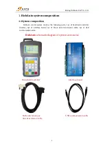
Страница 9: ...ontains the following parts 1pc of hand held controller handle 1pc of interface board 1pc of 50 pin data transmission cable 1pc of USB communication cable RichAuto schematic diagram of system accessories Hand held controller Interface board Both ends tenon type USB communication cable data transmission cable ...

Страница 10: ...he card reader throw over access port It can identify the files from external memory System format is FAT16 32 format This part can be removed separately if it is damaged 4 RichAuto LOGO 5 50 pin cable socket To realize the connection between the system and the machine tool via 50 pin cable The motion signal given by the system is transmitted to the machine tool motion actuator 6 USB communication...

Страница 11: ...utput signal terminal To control spindle ON OFF and spindle speed shifts etc Input signal terminal The input end of machine origin tool setting servo driver alarm hard limit E stop foot switch signals Power supply terminal The input terminal of system switching mode power supply DC 24V 3A Motor driver control terminal Driver control signal output terminals 1 3 Interface board installation dimensio...

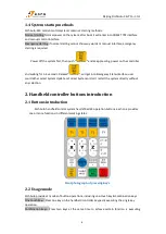
Страница 12: ...et into Emergency State interface user could either select System Update or Format System or don t restart the system directly without any selection 2 Handheld controller buttons introduction 2 1 Buttons introduction RichAuto handheld control system has defined 24 operation buttons each one provides one or more functions in different working states Real photograph of pressing keys 2 2 Usage mode R...

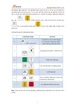
Страница 13: ...xiliary function key then at last release both of them at the same time Commonly used combination keys Combination Keys Function 1 0 9 numeric key Coordinates systems switching keys 0 is mechanical coordinate system 1 9are working coordinate system 2 Switching spindle shifts in manual mode 3 Repeat last processing 4 Set current position as parking position 5 System upgrade 6 Input coordinate param...

Страница 14: ...ion figure 3 7 input Set X axis and Y axis work origin figure 4 input Set work origin of Z axis Figure 8 input Operation of return machine zero point HOME in manual mode Figure 8 input FAST LOW motion state switching in manual mode work coordinate mechanical coordinate switching in auto mode figure 0 input Decimal input spindle ON OFF in manual mode Enter MENU setting View work information during ...

Страница 15: ... adjustment in manual mode processing termination Cancellation of various options inputs and operations during processing Switch to spindle No 1 Switch to spindle No 2 Switch to spindle No 3 user defined Enable Z axis automatic tool setting function Enable advanced processing function Repeat machining same processing file Breakpoint processing combination main function key support the figure 1 to ...

Страница 16: ...rface board terminal X axis signal output terminal Y axis signal output terminal Z axis signal output terminal C axis signal output terminal 24V power supply input terminal Analog output terminal Output signal connecting terminal Input signal connecting terminal ...

Страница 17: ... other voltage on this pin PULSE Yaxis pulse signal Output voltage 3V Drive current 8mA DIR Yaxis direction signal Output voltage 3V Drive current 8mA SHIELD Shield signal Y axis driver signal output shield wire Do not use this port as a ground port Z_AXIS 5V Zaxis common anode signal Z axis driver common anode power supply terminal 5V output Do not impose any other voltage on this pin PULSE Zaxis...

Страница 18: ...ntrol system realizes its control through the connection between the interface board and CNC machine Interface board terminal can be divided into input terminal and output terminal Input terminal INPUT SIGNAL terminal Main power supply terminal Output terminal X Y Z C axis pulse signal output terminal OUTPUT SIGNAL terminal Input terminal Main power supply wiring INPUT terminal wiring 1 Return ZER...

Страница 19: ...late 3 X5 X8 Default low level normally open Take the driver alarm as example The alarm signal is normally closed wiring method is series connection Meanwhile revise the voltage definition of X5 If the alarm signal is normally open the wiring method is parallel connection See as below ...

Страница 20: ...lse signal wiring is the same to X axis Step drive Servo drive Σ 7 and Σ V are the same wiring method Brake wiring Yaskawa servo Σ V series driver First ensure that the brake output is enabled and then set Pn50F to 0300 and select brake signal output terminal CN 29 and CN 30 Wiring is as follow ...

Страница 21: ...uble cylinders multi spindle cnc machine since the 4 cylinders multi spindle cnc machine wiring is the same 1 2 spindle with a single frequency converter Analog 2 2 spindle with 2 frequency converters Analog wiring To complete the above wiring the machine and control system will be connected with each other ...

Страница 22: ...f machine origin coordinate enter into MENU machine setup Home setup Home direction to set HOME direction 3 Double press manual voltage setup the upper arrows stand for input voltage to check whether the home switch is working properly manually trigger arrow flip We could determine the machine has been properly connected if all above are ready 4 MENU description 4 1 MENU classification RichAuto B1...

Страница 23: ...nd modify it under the guidance of the technical engineer Menu structure of Machine Setup Pulse Equivalent Linear axis The number of pulses required to send from the system when machine moves every 1mm Unit pulse mm Rotating axis The number of pulses required to send from the system when machine rotate every 1 degree Unit pulse degree For the computing method please see in SP7 Machine Setup Pulse ...

Страница 24: ... Save all changes and go back to the Table size menu Spindle Setup Spindle delay Including start delay and stop delay Unit ms Spindle state To be used to set multi speed control or simply spindle on off signal control parameters System defaults 3 line8 state if user needs 1 line2 state On Off just change the number of lines to 1 See detailed settings at OUTPUT SIGNAL spindle output wiring Home Set...

Страница 25: ...ationary state Not starting from 0 but starting directly from a certain speed so it can shorten the overall processing time but this speed shouldn t be too high Too high it will cause the motor losing steps jitter and even whistle Set too small it will reduce the operating speed of the entire graph If the inertia of motion axes is heavy shaft very heavy can set a smaller starts peed if the inertia...

Страница 26: ...eed in manual mode System defaults max speed X Y are60000000 mm min Z is 1800mm min Z is 3000 mm min Tool Count Tool count Input tool count here Max 4 tools Tool offset as below a X Y direction offset Method 1 Input directly by measurement Compared with the A15 the offset setting method of B15 is a little different We take 2 cutters for example the same setting method for 4 cutters In A15 the offs...

Страница 27: ... canceled Move the tool nose of spindle No 2 to the position where spindle No 1 leaved a knife mark If the X axis value displays 200 000 means that the distance between T1 and T2 is 200mm The X axis offset of T2 should be input as follow b Z direction offset Stressed manual tool changing process will move Z up to the highest point actually it s the Z axis zero point and then it switches to another...

Страница 28: ... Firstly set tool setting type into Auto under System Setup Function Confi ToolSet this operation can be carried out independently on different cutter heads but A15 must handle all of the tool heads simultaneously For B15 switch to the corresponding cutter head which needs offset value setting and then manually move down Z axis to reference surface for measuring Note All cutter heads must use the ...

Страница 29: ...n Enable or disable each input port by the user You could disable X5 X8 if there is no signal on these ports by yourself Input Configuration Enable or Disable the input port signals If X5 X8 have connect signal could disable X5 X8 signal under this menu 4 2 2 Auto Pro Setup This menu is used to set processing parameters G code attributes etc Menu structure of Auto Pro Setup Work Speed Unit mm min ...

Страница 30: ...e fall height Stop Statue Stop position when the processing is finished You can set either a special location or system specified location FinAct Final Action Coordnt coordinate Set a special stop position Press move cursor to where user wants to modify Press input new coordinate values one by one then press to save the changes Set system specified location Move the cursor to the first row and pre...

Страница 31: ...nge Return to the upper menu G Code Setup Set special G code attribute according to the actual need to make changes Ign Ignore Adj Adjt Adjust AbsCntr Absolute center PS Blue parts indicate system default attributes Setting Press move cursor to where needs to modify press and select then press to save Return to the upper menu Pro Attribute ...

Страница 32: ...tween the Ytrend of the file Total Processing times columncount Rowcount Time Interval System default 0 it means not wait During processing if user wants to change processing materials aftercompletion of each processing needs to set time interval as a negative number Whenthe first time processing is completed the screen prompt Waiting for the next array processing at this moment user should press ...

Страница 33: ...the internal files it will not remove the system parameters after inner format Wipe Cache The system needs wipe cache when it has been using for a long time or after the system upgrading it will ask to reboot after Wipe Cache operation System Setup Languages Data Initial Inner Format Wipe Cache Funtion Configuration Probation Password Backup Password Input port list Output port list Buttons Check ...

Страница 34: ...form RichAuto the original 20 digits password which displays on the system screen and then get new 20 digits from us to input into the controller to unlock all passwords Setting Press to enter into Probation Password input new password directly and then press to save Backup Password In condition of system parameters are disordered to avoid incorrect operation such as covering off the correct syste...

Страница 35: ...rameters by choosing the data bak file from the U disk or internal storage area Trial setting There are 4 grades of password Level 1 level 2 level 3 and level 4 Each level can be set password and use time User can set 1 8 digits Using time unit is Hour and the system defaults use time is 1h When the previous password expires the next level of password will come into effect The operation of Data In...

Страница 36: ...act us and tell us 20 digit original password under System Setup Probationpas menu and then obtain new 20 digit password from us enter the new numbers and press to remove 4 grade password and reset them Auto Upgrade If we added new functions we will offer upgrade file which extension name is PKG format File name is rz xxxx or q13 xxxx User could update the system through U disk for more details pl...

Страница 37: ...ed when power off Check Pro Time Check Processing Time Calculate processing time in accordance with the work speed After reading G code the screen will display the processing time Operate method Press to enter into Check Pro Time then press and select U disk Internal Recent file press and then choose a file press After reading the G code the screen will display the processing time PS Please pull o...

Страница 38: ...play all axis home Z home only none axis home after starting up the DSP handle Choose any one you want Machine return home can correct the coordinate of system In some cases such as after normal power off reboot and continue last operation no need to go machine ZERO just choose none axis home to skip HOME operation That is because system automatically saves coordinate value when the system exits n...

Страница 39: ...tus show on screen determines the actual manual moving speed 2 Speed adjusting In manual mode press enter into the current speed mode settings For instance suppose the current speed mode is LOW screen shows L the screen displays The cursor is on X SLOW Press to the one needs to be modified and press then input new value and next press to confirm Press to exit the settings If the input value is wro...

Страница 40: ...until the key is released The motion speed is determined by current manual speed mode 2 Step motion mode In step mode move 1 grid every half second The grid distance is determined by the current speed mode It is suitable for precise adjusting the cutter orfine adjusting the location of the mechanical coordinate 3 Distance motion mode It runs a certain distance according to the setting Press motion...

Страница 41: ...gin of coordinate is the origin of the machine or called reference point So at any time a point in space can be uniquely determined by a mechanical coordinate system Because of reference point is the calculation basis of machine coordinates movement all of those operations such as power on the machine or abnormal release and so on have to return to the reference point which is refers to return mac...

Страница 42: ...m parameters correctly Auto processing steps could refer to the following text 5 4 1 Set workpiece origin The origin coordinates of X Y and Z axis in the processing program is workpiece origin Before processing we should pay attention to this position as well as the real position Operation is as follow Move X Y and Z to the position which will start to process the file on workpiece Afterwards pres...

Страница 43: ...ve the cursor press to exit 5 4 3 Set processing parameters After selecting object file press the user can modify processing parameters including work speed fast speed speed scale and fall down scale Press move cursor to select different settings press input values and then press to confirm the changes The system starts to check the codes and machine SelectWorkFile Internal File Recent File U Disk...

Страница 44: ...d current line number Switching those options by pressing 5 5 Processing operations 5 5 1 Speed ratio spindle state adjusting 1 Speed ratio adjusting During processing press adjust the speed ratio The speed ratio increase decrease 0 1 each press on Speed scale speed ratio max 1 0 min 0 1 speed values are also changed accordingly except for the time Current processing speed work speed speed scale 2...

Страница 45: ... press again screen shows The system asks the operator to confirm whether to save the modified position or not Press or key the system will start processing at modified position Press the system will go back to the suspend position before modifying 5 5 3 Breakpoint processing power failure recovery 1 Breakpoint processing If user press during machine running the controller screen shows as below If...

Страница 46: ...cut key the screen shows the file name of on breakpoint 1 as below The G code file Testfile cnc for example it has totally 6705 lines g codes Press the screen displays breakpoint line No after pre reading Press popup machining parameters list then revise as needed and press the system will resume processing from breakpoint 1 However if user needs to go backwards from this breakpoint shall press th...

Страница 47: ... Before that system must have a HOME motion Shown as below Press key to start processing the unfinished process it will display stop line no and the line no also can be chosen Press cancel the power off protection If here the user wants to go backwards from current position the operate method is the same to what has mentioned in breakpoint processing 5 6 Advanced Processing Function Advanced proce...

Страница 48: ...ameters revise array parameters or go to MENU AUTO PRO SETUP choose Work Array and modify the array parameters The rest steps are similar to the normal processing After that system will start the array work according to the user s settings 4 During array work press view real time row number column number and other processing information Advanced Work Array work Resume work Tool changing Part work ...

Страница 49: ...essing from the new line For specification operation steps can review the contents in 5 5 3Breakpoint processing power failure recover 5 6 3 Tool changing It means manually loading or unloading the cutting tool in a certain position of the machine tool Press to get into the setup after changing the tool bit press to move back to the previous location 5 6 4 Part work Park work means user can select...

Страница 50: ... input an end line number and press to save it If the input value is wrong could press key and revise before confirm 4 Set processing parameters The rest steps are consistent with the common processing 5 6 5 Calculate bound Calculate bound means user can check the size of processing So as to avoid unnecessary waste of materials and machining errors The steps are as below 1 Press to move the cursor...

Страница 51: ...tio feed ratio 3 Press to move the cursor and press to modify parameters press to save all the changes b Encircle milling 1 Press to move cursor to choose the mill type as Encircle milling Scan mill set ScanType X Scan Width 100 000 Height 100 000 Diameter 10 000 Depth 0 00000 Z Step 0 100 T Ratio 0 800 Scan mill set ScanType AC anticlockwise Width 100 000 Height 100 000 Diameter 10 000 Depth 0 00...

Страница 52: ...respond to different processing time 5 6 8 Find break No During processing if accidentally tool damaged and user hasn t saved the break point stop working and replace cutter tool After that user can manually move X Y axis to the nearest point where the cutter was broken recommend to move a little further press to start advanced work move cursor to Find break no then press to enter in After guide a...

Страница 53: ...system 5 6 9 Scale work If the actual processing requires different sizes of the same file user can use scale work and enter a zoom in out ratio Steps Press to get into Scale work After changing all the value user could start the scale work machining Scale work param X scale 1 000 Y scale 1 000 Z scale 1 000 ...

Страница 54: ...s in U disk storage area and select relative upgrade pack then press the system will complete the updating automatically 4 When the upgrading is successful user should restart the controller Way 2 1 Store the PKG file Upgrade package into U disk and insert the U disk in the top right port on handheld controller The upgrade pack name in the controller is rz xxxx or qxx xxx 2 press the screen shows ...

Страница 55: ...disk the machine can still work normally Operation step 1 Press any two buttons at the same time for example 2 Connect handle and computer by USB cable it means that the handleis powered by computer loosen the buttons after the power supply 3 Handle screen display The handle is connected with the computer successfully 4 Open could find a removable storage device A0131482 G is the handle storage sp...

Страница 56: ...ring and parameters setting PS3 1 YASKAWA Σ 7 Σ series driver 1 Wiring Y Z same to X Set the driver as internal enable No need to connect pin 40 settings please see Pn50A which is in following table parameter setting Motor brake Σ 7 same as Σ Ⅴ ...

Страница 57: ...e of 1 65536 Pn210 Electronic gear ratio denominato r Need calculation Pn50A Input signal selection 1 8170 Bit 1 Set 7 servo on all the time Bit 3 Set 8 positive rotation not used and signal input P OT prohibited Pn50F Output signal selection 2 0300 Set it when servo motor with brakes Bit 2 Set 3 brake interlock signal BK is output from CN1 29 CN1 30 to control 24V relay used for brake Pn50E Outpu...

Страница 58: ...del to normally closed Press and flip the arrow to go upwards Arrow downwards normally open Arrow upwards normally closed PS3 2 PANASONIC MINAS A5 series servo driver 1 Wiring Y Z same as X Set the driver as internal Enable No need to connect pin 29 settings please see Pr4 05 which is in the following table of parameter setting Motor brake ...

Страница 59: ...mmand pulse frequency multiplication Need calculatio n Range 0 230 Z1 Encoder resolution Z2 Pulse equivalent Screwpitch Transmission ratio e g Pulse equivalent 1000 Screw pitch 10mm Encoder resolution 10000 Transmission ratio 1 Z1 Z2 10000 1000 10 1 1 1 set Pr0 09 1 set Pr0 10 1 The numerator and denominator of electronic gear ratio is reducibleto set the value of Pr0 09 and Pr0 10as integer range...

Страница 60: ...same as X Set the driver as internal Enable No need to connect pin 9 settings please see P2 10 which is in the following table of parameter setting Note A2 series PULSE PULSE SIGN SIGN correspond pin 43 41 36 37 COM corresponds pin 45 47 49 Motor brake A2 series BK BK correspond CN1 1 26 ...

Страница 61: ... set P1 44 2 P1 45 1 The numerator and denominator of electronic gear ratio is reducible P1 45 Electronic gear ratio denominator Z2 Need calculation P2 10 Function setting for digital input pin DI1 1 Bit 0 Set 1 servo on all the time If connect external enable signal Bit1 0 set 01 refers to the input digit input DI1 as SON correspond CN1 PIN 9 Bit2 set 1 indicate input DI1 as normally open a conta...

Страница 62: ...otation CCW from the view of load Bit 1 0 00 position control mode P1 44 Electronic gear ratio numerator Z1 Need calculation Range 1 32767 Z1 Encoder pulses 4 Z2 Pulse equivalent Screw pitch Transmission ratio e g Pulse equivalent 1000 Screw pitch 10mm encoder pulses5000 Transmission ratio 1 then Z1 Z2 5000 4 1000 10 1 2 1 Pn1 44 2 Pn1 45 1 The numerator and denominator of electronic gear ratio is...

Страница 63: ...meter will take effect when power on again PS4 G code reference list G code list of A1X A5X G00 Rapid positioning G01 Linearinterpolation G02 Circular interpolation CW G03 Circular interpolation CCW G04 Dwell Unit millisecond G17 Selection of XY coordinate plane G18 Selection of ZX coordinate plane G19 Selection of YZ coordinate plane G20 Input in inch G21 Input in metric G28 Auto back to referenc...

Страница 64: ... backing home G102 Move with fast speed until the signal is triggered Meanwhile Rollback and pinpoint signal edge similar to backing home G103 Move with processing speed until the signal is triggered G104 Move with fast speed until the signal is triggered M03 Spindle on CW rotation M04 Spindle on CCW rotation M05 Spindle stop M06 Tool change M08 Coolant on Flood M09 Coolant off M30 End of program ...

Страница 65: ... speed F Feed rate H Tool length offset PS5 Tool setting methods detailed explanation The process of tool setting is process of setting work coordinate system specific location in the machine tool coordinate system There are 3 kinds of tool settings Direct tool setting Fixed calibration and Mobile calibration Microset tool touch plate working sketch PS5 1 Direct tool setting Z axis move down towar...

Страница 66: ... tool setting input signal X4 is normally open state when ex factory Normally open type The microset signal CUTTER should be connected to the wiring board input port X4 COM connects to GND INPUT SIGNAL X4 system default normally open Normally closed Firstly modify the input voltage level of X4 to normally closed then connect CUTTER signal to X4 COM to GND INPUT SIGNAL The Over travel protection si...

Страница 67: ...ace of workpiece and set workpiece origin of X Y Z axis Press execute the first time tool setting The system will record value of offset automatically Start the processing after first time tool setting After the tool changed or tool bit broken press to start second time tool setting system will automatically restore to current Z axis workpiece coordinate origin Second time tool setting completed s...

Страница 68: ...ft up tool setting complete Note After connected the tool touch off plate start the machine don t start the spindle Don t put alligator clip on the spindle immediately but to start automatically tool setting function first and then use the alligator clip touch the tool touch off plate quickly in order to check whether Z axis has the action of tool setting To ensure there is no problem with the spi...

Страница 69: ...straight drive rack module gear teeth number π mechanical transmission ratio reduction ratio Rack helical drive rack module gear teeth number π mechanical transmission ratio reduction ratio cos helical angle Pulley belt drive π pulley diameter mechanical transmission ratio reduction ratio Screw drive E g 1 Driver nameplate 1 E g 2 Driver nameplate2 Motor nameplate stepper angle 1 8 Explain Stepper...

Страница 70: ...200 The use should use correct computational method according to the actural marks of stepper motor driver nameplate Screw pitch above picture The distance that the nut moves when the ball screw makes one rotation Transmission ratio The reduction rate or angular velocity ratio of the front drive sprocket to the end driven wheel Rack drive Straight teeth Helical teeth Explain Rack module and gear t...

Страница 71: ...rive screw pitch 5mm pulse equivalent 320 Rack drive rack module 1 25 gear teeth number 23 π 3 141592654 transmission ratio 1 5 0 2 helical angle 19 31 42 19 52833333 Straightrack Pulse equivalent 88 573 Helical rack Pulse equivalent 83 478 NOTES 1 25 23 3 141592654 0 2 18 0641577605 cos 19 52833333 0 94247630504668681677372940102406 1 25 23 3 141592654 0 2 cos 19 52833333 19 1666969915 19 1667 ...

Страница 72: ...crew pitch mechanical transmission ratio Straight rack pulse equivalent rack module gear teeth number π mechanical transmission ratio Helical rack pulse equivalent rack module gear teeth number π mechanical transmission ratio cos helical angle Pulley belt drive pulse equivalent π pulley diameter mechanical transmission ratio PS6 2 2 Calculate electronic gear ratio according to fixed pulse equivale...

Страница 73: ...ivalent default N 160000 A2 Encoder pulses equivalent default N 1280000 E g B2 series N 160000 Screw drive screw pitch 5mm Denominator M 1000 5 5000 Electronic gear ratio Set P1 44 32 P1 45 1 Rack drive rack module 1 25 gear teeth number 23 π 3 141592654 transmission ratio 1 5 0 2 helical angle 19 31 42 19 52833333 Straight rack Denominator M 1000 1 25 23 3 141592654 0 2 18064 Electronic gear rati...

Страница 74: ...on ratio 1 5 0 2 helical angle 19 31 42 19 52833333 Straight rack results retain up to three decimal places Pulse equivalent 553 582 Helical rack results retain up to three decimal places Pulse equivalent 521 738 PS6 2 4 Rotation axis Electronic gear ratio denominator Pulse equivalent 360 transmission ratio reduction ratio 1 Pulse equivalent of handle fixed to1000 YASKAWA Same to linear axis YASKA...

Страница 75: ...t can be calculated according to the proportion method Suppose handle pulse equivalent is A press switching to distance mode set a distance B measuring the number of actual moving distance C then the actual pulse equivalent A B C For example Suppose handle pulse equivalent A 400 distance B 100 actual distance C 80 then the actual pulse equivalent 400 100 80 500 Repeat calculation for several times...

Страница 76: ...ttons are broken Go to SYSTEM SETUP Buttons Check menu to check whether the buttons are normal or not 3 Assertion error Assertion error occurred during the processing or after starting is generally a software problem User can boot the controller by entering emergency state or re upgrade it If can t be solved either user should send back it for repairing 4 Unable to read U flash disk or read error ...

Страница 77: ...to confirm the actual position Solution is to go machine ZERO 2 The reserved processing range is small than the actual file size after user set work piece origin Confirm the actual file size and then set a correct working origin 3 Set wrong working origin in the process of creating processing file path Check the file path and then generate the correct one 3 Hard limit triggering 1 If the machine h...

Страница 78: ...ing error each time Replace a high quality detection switch 3 Too much interference in the Z axis homing process to form a false Z origin Re adjust the wiring 6 The machine cannot stop after returning ZERO and cause spindle hit the machine body Double press to check input signal Origin detection switch signal To do self test Detect whether the signal is triggered or disconnected 1 The origin detec...

Страница 79: ...g the inverter and other components should be separated connected each GND of themselves 3 There is something wrong while converting the file format and the program appears illegal characters or system unrecognized codes Recommended to use third party simulation software to review the program paths 9 Start automatic tool setting the tool does not stop after touching C A D Tool sensor 1 The cutter ...

Страница 80: ...eck if the coupling units loose or not 3 Increasing the start speed avoid the resonance point PS7 3 Electrical components and wiring problem 1 A single axis or multi axis can only in one direction after machine power on 1 There is something wrong with the connecting between the interface board and motor driver common anode end check the connection 2 Interface board is broken Replace the interface ...

Страница 81: ...creen display Spindle on actually the spindle off the screen display Spindle off actually the spindle on 1 Line fault Spindle on signal and COM port is short circuit Check circuit line 2 The output level definition reversed Go to the voltage setup and modify the output level definition modify the left first arrow direction in the second row 6 The handle screen doesn t light up and shows nothing af...

Страница 82: ...ne 3 Check interface board Press to start spindle use multimeter to measure Y1 and GND to see whether conducting if not interface board or 50 pin cable is broken To replace a new one for trouble clearing one by one Thank you for your support ...

Отзывы: