background image

 
DEPTH GATES AND HEAD TILT 


SeaBat 8160 

Operator‟s Manual 

Page 46 

October 6, 2011 

Version 5 


Sonar Head

MinDepth

MaxDepth

Line A


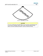
Figure 20: Depth Gates with Roll Input 

 
When controlled by a motion sensor, the depth gates will be parallel to the local 
horizontal plane of the earth, even as the vessel rolls.  
 

Sonar Head

MinDepth

MaxDepth

Line A


Figure 21: Depth Gates with Roll and Motion Sensor Input 


A.3  Offsetting the Sonar Array 

In the case of a sonar array mounted so as to look at a river bank or under a 
wharf structure, this discussion assumes a thirty degree offset to starboard. If the 
offset value of this mounting configuration is not identified properly, the ends of 
the swath may be cut off by one or both of the depth gates intersecting the 
bottom display even when a motion sensor is used. 
 

Содержание SeaBat 8160

Страница 1: ...SeaBat 8160 Operator s Manual Drawing Number 11282 October 6 2011 Version 5 Part Number 86010021 SeaBat 8160 Multibeam Echo Sounder System OPERATOR S MANUAL...

Страница 2: ...SeaBat 8160 Operator s Manual Drawing Number 11282 October 6 2011 Version 5 Part Number 86010021 This page intentionally left blank...

Страница 3: ...oleta California 93117 Telephone 805 964 6260 Facsimile 805 964 7537 Web http www reson com E mail sales reson com support reson com Copyright Release No part of this technical manual may be copied or...

Страница 4: ...SeaBat 8160 Operator s Manual Drawing Number 11282 October 6 2011 Version 5 Part Number 86010021 This page intentionally left blank...

Страница 5: ...r Processor 4 2 2 1 Technical Specifications 4 2 2 2 Illustrations 5 2 3 Transceiver Unit 6 2 3 1 Technical Specifications 6 2 3 2 Illustrations 7 2 4 Processor to Transceiver Interconnection Cable 8...

Страница 6: ...18 4 3 3 Orientation 19 4 3 4 Acoustic Center 20 4 3 5 Cable Connections 20 4 4 System Checkout 22 5 SYSTEM OPERATION 24 5 1 Chapter Overview 24 5 2 Start Up Procedure 24 5 3 Main Sonar Display Screen...

Страница 7: ...rs Menu 32 5 7 1 Apply a Filter Filter 33 5 7 2 Set Range Filter Limits MinRange MaxRange 33 5 7 3 Set Depth Filter Limits MinDepth MaxDepth 33 5 7 4 Correct for a Tilted Sonar Array HeadTilt 33 5 8 M...

Страница 8: ...s for SeaBat Firmware 106 E 3 Extended Warranty Contract 106 E 4 Telephone Support and Firmware Upgrades 106 E 5 SeaBat Cables 106 E 6 System Integration and Tuning 106 E 7 24VDC Power Supply for Sona...

Страница 9: ...Position 27 Figure 15 Typical Sound Velocity Values 31 Figure 16 Built In Test Environment BITE Display 35 Figure 17 Ping Indicator 36 Figure 18 Receiver Gain Offsets 39 Figure 19 Depth Gates No Roll...

Страница 10: ...le 8 Serial Port 1 Specifications 52 Table 9 Serial Port 2 Specifications 53 Table 10 Serial Port 3 Specifications 53 Table 11 Downlink 1 Specifications 54 Table 12 Straight Through Cable Specificatio...

Страница 11: ...and follow the steps provided to maintain optimal safety standards and to obtain the best system performance 1 2 1 Standards of Measurement All physical measurements represented in this document are b...

Страница 12: ...ox may prove harmful to personnel working with or near the system 1 2 4 Chapter Arrangement All RESON manuals are designed with the same basic structure The following chapters are included in this doc...

Страница 13: ...design drawings of system components Options and Upgrades A brief listing of options and upgrades available with your SeaBat system Snippets Sidescan Backscatter Detailed discussion of the snippets a...

Страница 14: ...the received hydrophone signals Processes the beamformed signals to produce bottom range information for each beam Manages seafloor bottom detection graphical user interface and serial communications...

Страница 15: ...cs 8 bit RGB Input Device Trackball mouse or remote commands Mounting 19 inch rack Dimensions Width 483mm Length 496mm Height 177mm See Figure 1 for details Weight 20kg Temperature Operating 0 to 40 C...

Страница 16: ...ector array Receives reflected acoustic pulses from the receive array Amplifies band shifts and multiplexes hydrophone signals then sends them to the sonar processor via the signal and control cable N...

Страница 17: ...Page 7 October 6 2011 Version 5 Specification Value Dimensions Width 483mm Length 497mm Height 267mm See Figure 3 for details Weight 13 6kg Temperature Operating 0 to 40 C Storage 30 to 55 C 2 3 2 Ill...

Страница 18: ...cables up to 150 meters may be ordered from RESON and will require adjustments to the hardware 2 5 Sonar Array The sonar array transmits acoustic energy then receives the returning signal pre amplifi...

Страница 19: ...Bottom Detect Range Resolution 750 meters 1 4cm 1 000 to 1 500 meters 2 9cm 1 750 to 5 000 meters 8 6cm Ping Rates See Appendix B Swath Coverage 130 with maximum swath width of approximately 4 times...

Страница 20: ...will increase to as much as 8 0 at the outer edges of the swath 2 5 2 Illustrations Figure 5 Sonar Array Assembly 2 6 Peripherals 2 6 1 Color S VGA Monitor The color monitor supplied with the SeaBat...

Страница 21: ...11 October 6 2011 Version 5 2 6 2 Trackball The trackball supplied with the SeaBat system is a three button unit that has been modified by RESON for use with the sonar processor In the event of damage...

Страница 22: ...to operator safety as well as protection of the hardware components General precautions include DO NOT connect or disconnect cables with power on DO NOT attempt to open and service the sonar array DO...

Страница 23: ...e may be scratched or damaged If an array must be placed on the ground it should be placed on a flat surface and covered with a protective plastic sheet Do not place liquids on or near the equipment D...

Страница 24: ...g hot or cold pressure washers The high velocity water spray will cut through the polyurethane or damage the interface between the polyurethane and the sonar metal housing To scrape away marine growth...

Страница 25: ...effects continued exposure to ultraviolet UV rays will damage the polyurethane array face 3 6 Safe Disposal of Waste WEEE Directive The use of the crossed out dustbin logo indicates that this product...

Страница 26: ...round the unit to provide adequate air circulation and easy access to the power switch Once the sonar processor is installed the only interaction required should be to depress the power switch and ene...

Страница 27: ...onnections to be made at the dry end of the installation These connections are between the sonar processor and its peripheral equipment and between the sonar processor and the transceiver The critical...

Страница 28: ...rray may be attached to a pole or mounting structure with the supplied mounting bracket using M10 bolts Mounting may be over the side over the bow or through a moon pool The sonar array should be imme...

Страница 29: ...oriented vertically downwards In the ideal configuration the receive array will be mounted across track while the transmit array will be mounted along track and aft of the receive array Figure 9 Recom...

Страница 30: ...center location The acoustic center is located inside the projector array at the intersections of lines X Y and Z Forward Y Z Acoustic Center Sonar Head Top View Y X Acoustic Center Projector Cross Se...

Страница 31: ...the Transmit and Control Port J5 on the transceiver rear panel Figure 12 4 3 5 2 Transmit Array Cable The transmit array cable Figure 42 is molded to the transmit array at the wet end and splits into...

Страница 32: ...cessor to energize the system 6 Immediately check the Transmit Power TxPower to make certain it is set to off Prolonged transmission in air even at a low setting will damage the transmit array ceramic...

Страница 33: ...at a time The click rate should increase as the range scale decreases 8 As soon as the test is complete turn the Transmit Power TxPower to the OFF setting so as to avoid damage to the transmit array C...

Страница 34: ...gized the sonar processor will start the SeaBat firmware and calibrate the electronics associated with each of the ceramic elements in the receive array CAUTION Do not power up reboot or calibrate the...

Страница 35: ...Depth Z and Range R of a particular point on the sonar image see Figure 13 The Cursor Position Block will change as the mouse pointer passes over the sonar image indicating the X Z and R of the pointe...

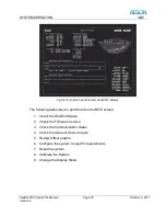
Страница 36: ...ve separate menus that may be found in the Menu Block Those are Main Ocean Display Filters and Off 5 3 5 Activate the BITE Display The SeaBat 8160 includes a Built In Test Environment BITE display tha...

Страница 37: ...standard ping rates Select the appropriate range scale to keep the horizontal bottom image at or above the widest part of the sonar wedge 155 155 155 A B C Figure 14 Swath Position In Figure 14 above...

Страница 38: ...shorter range A wider Pulse Width will provide maximum range with lower resolution image results The TxPulse setting allows the operator to change the Pulse Width of the transmitted signal For a stan...

Страница 39: ...oss SP values may be modified using the Absorb and Spread items on the Ocean menu see section 5 5 Ocean Menu 5 4 7 Activate Automatic Gain AutoGain The Automatic Receiver Gain function analyzes the bo...

Страница 40: ...the Absorption Loss Value Absorb This selection allows the operator to enter the amount of loss expected through the ambient water medium The range available is from 0 to 120dB km If the exact value i...

Страница 41: ...nge the Color Scheme 2 Set the Contrast 3 Display or Hide the Sonar Grid 4 Freeze the sonar image 5 6 1 Change the Color Scheme Color Six pre set color schemes are available The color palette indicate...

Страница 42: ...en Phase detection c Cyan Blended magnitude phase detection 5 6 4 Display or Hide the Sonar Grid Grid The Grid selection allows the operator to control the display of the border and scale lines that a...

Страница 43: ...e range and depth minimum and maximum values None No filters are activated 5 7 2 Set Range Filter Limits MinRange MaxRange Only bottom returns within these range limits will be used in the bottom dete...

Страница 44: ...lue use the middle track ball button to increase the increment rate by a factor of ten When filter values are set via a remote source the increments can be reduced to 1 10 of the increments above 5 8...

Страница 45: ...play The following tasks may be performed on the BITE screen 1 Check the Wet End Status 2 Check the Firmware Version 3 Check the Communication status 4 Check the status of Sensor Inputs 5 Review Offse...

Страница 46: ...or 5 9 2 Check the Wet End Status This item displays information with regards to the status of the sonar array assembly Leak Shown as voltage the leak sensor indicates the presence of water in the son...

Страница 47: ...iver unit The indication will be either Good or Bad Internal Indicates the status of the sonar processor internal self test The indication will be either Good or Bad Ethernet This is the Ethernet hard...

Страница 48: ...d UTC Date The current UTC date from an external date time source if installed UTC Time The current UTC time from an external date time source if installed NOTE The velocity of sound at the face of th...

Страница 49: ...tion of offsets These values should be close to zero for all channels Click the CALIB button while holding down the center mouse button to present uncorrected values 5 9 7 Configure System to Specific...

Страница 50: ...n packets from a Data Acquisition System 5 9 7 5 Select the Control Message Baud Rate ContrlBD Allows control of the input baud rate for control messages from an external modem 5 9 7 6 Select Motion R...

Страница 51: ...specific vessel or platform 5 9 8 1 Select Packet Format Format Controls the format content of each output profile data packet R R Theta range and beam angle provides all soundings their quality value...

Страница 52: ...bottom detect point of any specific beam FlatBottm Outputs snippets the lengths of which are roughly proportional to the size of each beam s footprint on the bottom 5 9 8 5 Test the Projector Projectr...

Страница 53: ...he outer beams of the swath Roll Stabilization is limited to a practical value of 20 The RollStab menu option allows for the selection of Roll Stabilization options OFF Roll Stabilization is not used...

Страница 54: ...n the analogue receiver channels 5 10 Changing Display Mode To change the display mode move the cursor to the farthest point possible in the upper left corner of the screen and press the appropriate s...

Страница 55: ...be oriented parallel to the horizontal plane of the sonar array as shown by the Min and MaxDepth lines in Figure 19 In this series of illustrations the bottom detect dots are shown as a horizontal li...

Страница 56: ...lls Sonar Head MinDepth MaxDepth Line A Figure 21 Depth Gates with Roll and Motion Sensor Input A 3 Offsetting the Sonar Array In the case of a sonar array mounted so as to look at a river bank or und...

Страница 57: ...n added the only area of this new swath that will be visible is within the small box everything else will be removed by the action of the depth gates Sonar Head MinDepth MaxDepth Line B Figure 22 Dept...

Страница 58: ...ead M inDepth M axDepth Line B Figure 23 Depth Gates with Offset CAUTION The use of depth gates and other filters is a very delicate and potentially error prone process Exercise extreme caution when a...

Страница 59: ...cale Ping Rate1 Ping Rate2 5 14 94 14 94 7 14 94 14 94 10 14 94 14 94 15 14 94 14 94 20 14 94 14 94 25 14 94 14 94 30 14 94 14 94 35 14 94 14 94 40 14 94 13 26 50 12 88 10 84 75 8 84 7 41 100 6 73 5 6...

Страница 60: ...1 Version 5 NOTE The number of output profiles per second is primarily governed by the update ping rate which in turn is controlled by the range selected Ping Rate is determined by the Round Trip Time...

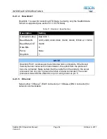
Страница 61: ...the serial ports that are assigned different tasks and data This section will cover six of the rear panel ports The network interface can only use one port at a time 1 RS 232 Serial Port 1 IN Time Sta...

Страница 62: ...Data Set Ready 5 GND Signal Ground 5 GND Signal Ground 6 DSR Data Set Ready 4 DTR Data Terminal Ready 7 RTS Request To Send 8 CTS Clear To Send 8 CTS Clear To Send 7 RTS Request To Send 9 Not Used 9 N...

Страница 63: ...Label RS 232 Port 2 Baud Rate IN 1200 2400 4800 9600 19200 38400 57600 or 115200 Baud Rate OUT 1200 2400 4800 9600 19200 38400 57600 or 115200 Data Bits 8 Parity None Stop Bits 1 C 2 1 3 Serial Port...

Страница 64: ...19200 38400 57600 or 115200 Baud Rate OUT 19200 Data Bits 8 Parity None Stop Bits 1 NOTE Downlink Port 1 continuously transmits downlink commands If the Sound Velocity Sensor receives this transmissio...

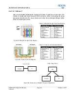
Страница 65: ...traight Through Cable Specifications Connector 1 Pin Connector 2 White Orange 1 White Orange Orange 2 Orange White Green 3 White Green Blue 4 Blue White Blue 5 White Blue Green 6 Green White Brown 7 W...

Страница 66: ...3 Messages and Data Format Messages and data are based on certain structures Each structure is described below C 3 1 Command Messages All command messages are based on ASCII strings and built on the f...

Страница 67: ...tomatic gain in the sonar processor Syntax AGAN N CR LF Parameters N 0 Off N 1 to 10 Set out threshold equal to selected numeric value Example AGAN 1 CR LF This example turns automatic gain on and set...

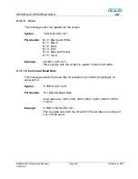
Страница 68: ...ud rate on Serial Port 1 to 115200 C 3 1 4 BITE Screen This message controls which screen should be presented Syntax BITE N CR LF Parameters N 0 Show Main Sonar Display N 1 Show BITE Display Example B...

Страница 69: ...ess than or equal to the maximum range Example BMIN 10 CR LF This example sets the minimum range filter value to 10m C 3 1 7 Contrast This message sets contrast brightness for the screen Syntax BRIT N...

Страница 70: ...e and Yellow N 5 Vivid Example COLR 1 CR LF This example sets the screen to appear in black and white C 3 1 10 Command Baud Rate This message selects the baud rate for reception of command messages on...

Страница 71: ...mping any data Syntax DATE Year Month Day CR LF Parameters Year In four digits Month Month 1 12 Day Day 1 31 Example DATE 2001 3 8 CR LF This example sets the date to 8 March 2001 C 3 1 13 Dot Check T...

Страница 72: ...o 100 meters C 3 1 15 Minimum Depth Filter This message sets the maximum value for the depth filter Syntax DMIN N CR LF Parameters N Min Depth Filter m The parameter may be any number from 0 to the ma...

Страница 73: ...20 pings per second C 3 1 18 Filter Setting This message selects the filters to be used Syntax FILT N CR LF Parameters N 0 No Filter N 1 Range Filter Only N 2 Depth Filter Only N 3 Both Filters Exampl...

Страница 74: ...he data on the screen C 3 1 21 Manual Gain This message sets the manual gain for the sonar processor Syntax GAIN N CR LF Parameters N Manual gain value Example GAIN 1 CR LF This example sets the 81 P...

Страница 75: ...ts the menu Syntax MENU N CR LF Parameters N 0 Main N 1 Filters N 2 Ocean N 3 Off N 4 Display Example MENU 0 CR LF This message sets the current menu to main menu C 3 1 25 Motion Sensor Baud Rate This...

Страница 76: ...1 Remote IP address data collection system PARAM IP address XXX XXX XXX XXX N 2 UDP port PARAM UDP Port XXXXX N 3 Gateway IP address router PARAM IP address XXX XXX XXX XXX N 4 Subnet mask PARAM Subn...

Страница 77: ...R LF For a SeaBat 8160 this example selects Steer 1 5 NOTE The projector selection varies for different SeaBat models This setting will only apply to the SeaBat model for which this manual was written...

Страница 78: ...Sets the sonar processor to output bathymetric packets in the R theta format C 3 1 31 Pulse Width This message sets the Pulse Width in seconds Syntax PWID N CR LF Parameters N Pulse width value in se...

Страница 79: ...e first exported beam to be 0 first beam C 3 1 34 Raw Output Mode Selection raw output only This message sets the raw output mode Syntax RAWM N CR LF Parameters N 0 No data exported N 1 16 bits magnit...

Страница 80: ...Example RSTB 1 CR LF Sets roll stabilization to mode 1 C 3 1 37 Snapshot This message tells the sonar processor to transmit a complete snapshot of beamformed magnitude and phase data over the network...

Страница 81: ...ld be multiplied by 4 0 to 240 0 0 to 60 0 log Range ABSORPTION The absorption value Range from 0 to 120 dB km Example STVG 20 60 CR LF This message sets Spreading Loss to 5dB and the absorption to 60...

Страница 82: ...BR 9600 CR LF This example sets the IN baud rate on Downlink Port 1 to 9600 C 3 1 42 Version This message returns the wet end and dry end software version Syntax SVER CR LF Parameters N A Example SVER...

Страница 83: ...or time not used for time stamping any data Syntax TIME HH MM SS CR LF Parameters HH Hours 0 23 MM Minutes 0 59 SS Seconds 0 59 Example TIME 13 42 1 CR LF The example sets the processor time to 13 42...

Страница 84: ...tern ON N any other value Turns the test pattern OFF Example TPAT 1 CR LF The message sets the test pattern ON C 3 1 48 Uplink This message selects the uplink port Syntax UPLK N CR LF Parameters N 0 C...

Страница 85: ...tion of SeaBat Data The SeaBat output message packets will always include a latency time the time interval between the sonar ping and the output of the first element of the data packet by the sonar Th...

Страница 86: ...SSS SSS Salinity Parts per Thousand VVVVV VVV Sound Velocity Meter per Second C 3 3 2 SeaBird CTD Message TTT TTTT CC CCCCC PPPPP PPP SSSS SSSS VVVVV VVV CR LF Table 18 SeaBird CTD Message Format Fiel...

Страница 87: ...Sign Convention for Sonar Processor C 3 4 1 TSS DMS05 Message XXAAAASMHHHHQMRRRRSMPPPP CR LF Table 20 TSS DMS05 Message Format Field Description Range Units Start of Message XX Horizontal Acceleratio...

Страница 88: ...Heave 99 to 99m 1cm S Space Character MRRRR Roll 90 to 90 0 01 MPPPP Pitch 90 to 90 0 01 M if positive or if negative C 3 4 3 TSS 332B Message MRRRRMPPPP CR Table 22 TSS 332B Message Format Field Des...

Страница 89: ...4 1 17 hex 11 header q replaced with Q when data is unstable i e at startup Table 23 Seatex MRU Message Format Field Units Format Bytes Value Header ASCII 1 ASCII q or Q Length Unsigned 1 0x11 Token U...

Страница 90: ...rge X1 in meters signed y yyy sway X2 in meters signed z zzz heave X3 in meters signed Syntax PHSPD x xxx y yyy z zzz hh CR LF Parameters x xxx X1 speed in m s 1 signed y yyy X2 speed in m s 1 signed...

Страница 91: ...ror Bit 14 Accelerometer X3 error Bit 15 Analog input A or B error Bit 16 Serial input A error Bit 17 Serial input B error Bit 18 Serial input C error Bit 20 Serial output A full Bit 21 Serial output...

Страница 92: ...Data Types DATA TYPE BYTES Char 1 Short 2 Long 4 C 3 6 1 Time Stamp The DATA_TIME Struct are used for time stamping struct DATA_TIME unsigned long Seconds Seconds since 00 00 00 1 January 1970 unsign...

Страница 93: ...15 0 manual 1 auto unsigned short pulse_width transmit pulse width microseconds unsigned char tvg_spread spreading coefficient for tvg 4 valid values 0 to 240 0 0 to 60 0 in 0 25 steps unsigned char...

Страница 94: ...tial ping number from sonar startup reset unsigned long sonar_id least significant four bytes of Ethernet address unsigned short sonar_model coded model number of sonar unsigned short frequency sonar...

Страница 95: ...first with the higher 4 bits for the first sounding and the lower 4 bits for the second sounding bottom detect can be amplitude phase or both unsigned short intensity n intensities at bottom detect 8...

Страница 96: ...e set range setting for SeaBat meters unsigned short power power setting for SeaBat unsigned short gain gain setting for SeaBat bits 0 6 gain 1 45 bit 14 0 fixed 1 tvg bit 15 0 manual 1 auto unsigned...

Страница 97: ...hort Latency time from ping to output milliseconds unsigned short SonarID 2 least significant four bytes of Ethernet address unsigned short SonarModel coded model number of sonar unsigned short Freque...

Страница 98: ...uential ping number unsigned short Beam beam number 0 N 1 unsigned short SnipSamples Snippet size samples unsigned short GainStart gain at start of Snippet 0 01dB steps 0 ignore unsigned short GainEnd...

Страница 99: ...nterfaces are described below C 4 2 Power The transceiver unit requires a nominal 24VDC for operation however a voltage range of 22 to 30 volts is acceptable C 4 3 Uplink Data The uplink between the t...

Страница 100: ...of frame up counter Reset to zero during ping 4 I value of receiver 0 5 Q value of receiver 0 6 I value of receiver 1 7 Q value of receiver 1 510 I value of receiver 253 511 Q value of receiver 253 Ta...

Страница 101: ...he uplink path are correctly terminated and shielded It is particularly important that a 75 ohm impedance be maintained throughout If impedance is mismatched it will cause signal degradation regardles...

Страница 102: ...11337 Wet End Array Installation Template Drawing 11411 Array Outline and Installation Drawing Drawing 0416M011_001 Array Section 1 Array Section 2 Array Section 3 Four Inch Flange Drawing 0416E121_00...

Страница 103: ...SYSTEM DRAWINGS SeaBat 8160 Operator s Manual Page 93 October 6 2011 Version 5 Figure 31 SeaBat 8160 System Sheet 1...

Страница 104: ...SYSTEM DRAWINGS SeaBat 8160 Operator s Manual Page 94 October 6 2011 Version 5 Figure 32 SeaBat 8160 System Sheet 2...

Страница 105: ...SYSTEM DRAWINGS SeaBat 8160 Operator s Manual Page 95 October 6 2011 Version 5 Figure 33 Array Installation Template...

Страница 106: ...SYSTEM DRAWINGS SeaBat 8160 Operator s Manual Page 96 October 6 2011 Version 5 Figure 34 Array Outline and Installation Drawing...

Страница 107: ...SYSTEM DRAWINGS SeaBat 8160 Operator s Manual Page 97 October 6 2011 Version 5 Figure 35 Array Section 1...

Страница 108: ...SYSTEM DRAWINGS SeaBat 8160 Operator s Manual Page 98 October 6 2011 Version 5 Figure 36 Array Section 2...

Страница 109: ...SYSTEM DRAWINGS SeaBat 8160 Operator s Manual Page 99 October 6 2011 Version 5 Figure 37 Array Section 3...

Страница 110: ...SYSTEM DRAWINGS SeaBat 8160 Operator s Manual Page 100 October 6 2011 Version 5 Figure 38 Four Inch Flange...

Страница 111: ...SYSTEM DRAWINGS SeaBat 8160 Operator s Manual Page 101 October 6 2011 Version 5 Figure 39 Projector...

Страница 112: ...SYSTEM DRAWINGS SeaBat 8160 Operator s Manual Page 102 October 6 2011 Version 5 Figure 40 Hydrophone...

Страница 113: ...SYSTEM DRAWINGS SeaBat 8160 Operator s Manual Page 103 October 6 2011 Version 5 Figure 41 Cable Hydrophone Dry End Termination...

Страница 114: ...SYSTEM DRAWINGS SeaBat 8160 Operator s Manual Page 104 October 6 2011 Version 5 Figure 42 Cable Projector Dry End...

Страница 115: ...SYSTEM DRAWINGS SeaBat 8160 Operator s Manual Page 105 October 6 2011 Version 5 Figure 43 Cable Processor to Transceiver shielded...

Страница 116: ...for the second and third year period E 3 Extended Warranty Contract All SeaBat systems are provided with a standard twelve month warranty see Appendix G Warranty Information This option provides the...

Страница 117: ...hat will function with an input voltage range of 18 to 72VDC At a nominal 24VDC the system requires a maximum of 240 watts E 8 Faired Mounting Assembly This option provides a faired frame for the rece...

Страница 118: ...F 1 Overview With the backscatter sidescan functionality a sidescan swath is measured and output from the sonar processor without degrading any of the traditional survey capabilities MBES Sidescan Ba...

Страница 119: ...g bottom detect point footprint location the combined series will provide a result similar to slant range corrected sidescan imagery see Figure 44 In most cases this will provide 100 coverage of the s...

Страница 120: ...y near the vessel out to the maximum slant range of the sonar Figure 46 Sidescan Beam Geometry Once the sidescan data is measured it is transferred to the topside processor where it is processed separ...

Страница 121: ...29 MBES Sidescan Specifications Specification Value Swath Width See Table 4 Range Resolution Range Sample Rate Resolution 5 750m 7109 375Hz 10cm 1 000 1 500m 3554 688Hz 20cm 1 750 5 000m 1184 896Hz 60...

Страница 122: ...range At a 1 000 meter setting using a 1 500 meter per second sound velocity the packet will have 4 738 values per sidescan beam The data is output in a series of binary packets via a network connecti...

Страница 123: ...turn of the products to the customer not including any duty and taxes G 2 Exclusions The warranty on your RESON system shall not apply to defects resulting from Improper use Improper or inadequate ins...

Страница 124: ...ctions in the supplied document and pack the equipment in the original shipping containers 3 Ship the equipment to your RESON representative to the applicable address 4 Ensure that the RMA number is i...

Страница 125: ...he following reference table Table 30 Metric Conversion Table Metric Unit Imperial Unit Millimeter mm 0 0394in Centimeter cm 0 3937in Meter m 1 0936yd Kilometer km 0 6214mi Kilogram kg 2 2046lb H 2 Te...

Страница 126: ...tems Some modern side scan type of sonar systems use two transducers per side to produce bathymetric data along with wide area imaging These systems although producing both types of data leave much to...

Страница 127: ...acoustic energy into the water see Transmit Array Pulse Width The distance of the ensonified water in the range dimension at a given point in time expressed in meters and determined by multiplying the...

Страница 128: ...y See Projector TVG Time Variable Gain control intended to vary the gain of an amplifier over a pre determined time period Usually from a low gain state to high gain UDP User Datagram Protocol Uplink...

Страница 129: ...SeaBat 8160 Operator s Manual Produced by RESON Inc 100 Lopez Road Goleta California 93117 United States of America Tel 1 805 964 6260 Fax 1 805 964 7537 Drawing Number 11282 Part Number 86010021...

Отзывы: