SYSTEM OPERATION
SeaBat 8160
Operator‟s Manual
Page 39
October 6, 2011
Version 5
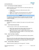
Receiver Phase Offsets:
Condition
Color
Value
Acceptable
Green
<
35
Marginal
Yellow
≥
35
to <
60
Extreme
Red
≥ 60
As the cursor is moved over the data, the Element number (receiver channel
location), the Offset Value, and the Median Value are displayed below the
selected graph block (see
Figure 18: Receiver Gain Offsets
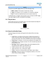
NOTE
The data initially shown in the offset graphs is the corrected Gain and Phase
offsets of the main receive array elements after the application of offsets.
These values should be close to zero for all channels.
Click the “CALIB” button while holding down the center mouse button to
present uncorrected values.
5.9.7 Configure System to Specific Requirements
The Config Menu allows the operator to integrate the SeaBat 8160 to any
vessel‟s specific requirements.
5.9.7.1
Select Uplink Port (Uplink)
Select the uplink port to be used.
5.9.7.2
Select Output Method (Output)
Select the method by which measured profile is output from the sonar processor:
RS-232:
Output via Serial Port #1 at the rear of the sonar processor.
Packets will be transmitted at the speed selected (ProfileBD) at an
interval based on the selected range and data rate (MaxRate), and in
Element Number
Offset Value
Median Value
Содержание SeaBat 8160
Страница 103: ...SYSTEM DRAWINGS SeaBat 8160 Operator s Manual Page 93 October 6 2011 Version 5 Figure 31 SeaBat 8160 System Sheet 1...
Страница 104: ...SYSTEM DRAWINGS SeaBat 8160 Operator s Manual Page 94 October 6 2011 Version 5 Figure 32 SeaBat 8160 System Sheet 2...
Страница 105: ...SYSTEM DRAWINGS SeaBat 8160 Operator s Manual Page 95 October 6 2011 Version 5 Figure 33 Array Installation Template...
Страница 107: ...SYSTEM DRAWINGS SeaBat 8160 Operator s Manual Page 97 October 6 2011 Version 5 Figure 35 Array Section 1...
Страница 108: ...SYSTEM DRAWINGS SeaBat 8160 Operator s Manual Page 98 October 6 2011 Version 5 Figure 36 Array Section 2...
Страница 109: ...SYSTEM DRAWINGS SeaBat 8160 Operator s Manual Page 99 October 6 2011 Version 5 Figure 37 Array Section 3...
Страница 110: ...SYSTEM DRAWINGS SeaBat 8160 Operator s Manual Page 100 October 6 2011 Version 5 Figure 38 Four Inch Flange...
Страница 111: ...SYSTEM DRAWINGS SeaBat 8160 Operator s Manual Page 101 October 6 2011 Version 5 Figure 39 Projector...
Страница 112: ...SYSTEM DRAWINGS SeaBat 8160 Operator s Manual Page 102 October 6 2011 Version 5 Figure 40 Hydrophone...
Страница 114: ...SYSTEM DRAWINGS SeaBat 8160 Operator s Manual Page 104 October 6 2011 Version 5 Figure 42 Cable Projector Dry End...

