INSTALLATION INSTRUCTIONS
SeaBat 8160
Operator‟s Manual
Page 22
October 6, 2011
Version 5
4.3.5.3
Sound Velocity Probe Cable
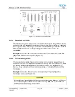
The Sound Velocity Probe (SVP) is normally connected at the rear panel of the
sonar processor. As a convenience, however, the Sound Velocity Probe may be
connected to the transceiver rear panel and a second cable fabricated on-site to
continue the link to the operating area. This precludes the requirement to have a
special cable attached to the sensor.
4.4 System Checkout
Once the components of your SeaBat 8160 system have been installed, follow
the steps in this section to ensure that the system is working properly.
1. Ensure all system cable connections are tight.
2. Verify that mains power is available.
3. Energize the monitor.
4. Ensure that the transceiver unit
power switch is in the “On” position.
5. Press the power switch on the sonar processor to energize the system.
6. Immediately check the Transmit Power (TxPower) to make certain it is set
to off. (Prolonged transmission in air
– even at a low setting – will damage
the transmit array ceramics.)
7. If a sound velocity probe and/or motion sensor are connected, ensure the
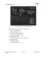
data is being correctly read. Do this by accessing the BITE display and
reading the values at the Sensor Input field. (See
section
Once the system has been energized, perform the following checks to verify that
the system is operating correctly:
1.
Make certain the Transmit Power is set to “OFF”.
2.
Set the Range to “100”.
3.
Set AutoGain to “Off," GainMode to “TVG," and RxGain to “45."
4.
Select the “Display” menu and ensure that “Color” is set to “BLU-YEL”
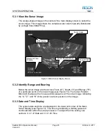
5. Perform a receiver check by vigorously rubbing the face of the receive
array with fingertips while monitoring the display. A noise pattern should
be visible on the display.
6. Gradually increase the Transmit Power while an assistant listens to the
projector. Stop when there is an aud
ible “clicking” sound.
Содержание SeaBat 8160
Страница 103: ...SYSTEM DRAWINGS SeaBat 8160 Operator s Manual Page 93 October 6 2011 Version 5 Figure 31 SeaBat 8160 System Sheet 1...
Страница 104: ...SYSTEM DRAWINGS SeaBat 8160 Operator s Manual Page 94 October 6 2011 Version 5 Figure 32 SeaBat 8160 System Sheet 2...
Страница 105: ...SYSTEM DRAWINGS SeaBat 8160 Operator s Manual Page 95 October 6 2011 Version 5 Figure 33 Array Installation Template...
Страница 107: ...SYSTEM DRAWINGS SeaBat 8160 Operator s Manual Page 97 October 6 2011 Version 5 Figure 35 Array Section 1...
Страница 108: ...SYSTEM DRAWINGS SeaBat 8160 Operator s Manual Page 98 October 6 2011 Version 5 Figure 36 Array Section 2...
Страница 109: ...SYSTEM DRAWINGS SeaBat 8160 Operator s Manual Page 99 October 6 2011 Version 5 Figure 37 Array Section 3...
Страница 110: ...SYSTEM DRAWINGS SeaBat 8160 Operator s Manual Page 100 October 6 2011 Version 5 Figure 38 Four Inch Flange...
Страница 111: ...SYSTEM DRAWINGS SeaBat 8160 Operator s Manual Page 101 October 6 2011 Version 5 Figure 39 Projector...
Страница 112: ...SYSTEM DRAWINGS SeaBat 8160 Operator s Manual Page 102 October 6 2011 Version 5 Figure 40 Hydrophone...
Страница 114: ...SYSTEM DRAWINGS SeaBat 8160 Operator s Manual Page 104 October 6 2011 Version 5 Figure 42 Cable Projector Dry End...


