INSTALLATION INSTRUCTIONS
SeaBat 8160
Operator‟s Manual
Page 16
October 6, 2011
Version 5
4 INSTALLATION INSTRUCTIONS
4.1 Chapter Overview
This chapter outlines basic information and technical specifications for the
components of your SeaBat 8160 system.
4.2 Dry End Installation
Following are instructions for use when installing the dry end components of the
SeaBat 8160
system.
4.2.1 Sonar Processor
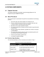
The sonar processor may be either rack- or table-mounted. It must be in an area
that is not exposed to the weather, but is within easy reach of both the operator
and the 20 meter transceiver to processor interconnection cable. Allow clearance
around the unit to provide adequate air circulation and easy access to the power
switch.
Once the sonar processor is installed, the only interaction required should be to
depress the power switch and energize the system.
4.2.2 Transceiver
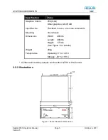
Due to the 15 meter length of the sonar array to transceiver cables, the
transceiver unit must be installed as close as possible to the sonar array. This
may be in a dry, unmanned equipment room as long as the ambient temperature
is taken into consideration (see
Table 3: Transceiver Unit, Technical
Allow clearance around the unit to provide adequate air circulation and to allow
for connection of cables without the need for sharp bends.
4.2.3 Peripherals
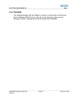
The monitor and track ball are the primary tools for the operator and should be
located in a comfortable work area near the sonar processor.
Содержание SeaBat 8160
Страница 103: ...SYSTEM DRAWINGS SeaBat 8160 Operator s Manual Page 93 October 6 2011 Version 5 Figure 31 SeaBat 8160 System Sheet 1...
Страница 104: ...SYSTEM DRAWINGS SeaBat 8160 Operator s Manual Page 94 October 6 2011 Version 5 Figure 32 SeaBat 8160 System Sheet 2...
Страница 105: ...SYSTEM DRAWINGS SeaBat 8160 Operator s Manual Page 95 October 6 2011 Version 5 Figure 33 Array Installation Template...
Страница 107: ...SYSTEM DRAWINGS SeaBat 8160 Operator s Manual Page 97 October 6 2011 Version 5 Figure 35 Array Section 1...
Страница 108: ...SYSTEM DRAWINGS SeaBat 8160 Operator s Manual Page 98 October 6 2011 Version 5 Figure 36 Array Section 2...
Страница 109: ...SYSTEM DRAWINGS SeaBat 8160 Operator s Manual Page 99 October 6 2011 Version 5 Figure 37 Array Section 3...
Страница 110: ...SYSTEM DRAWINGS SeaBat 8160 Operator s Manual Page 100 October 6 2011 Version 5 Figure 38 Four Inch Flange...
Страница 111: ...SYSTEM DRAWINGS SeaBat 8160 Operator s Manual Page 101 October 6 2011 Version 5 Figure 39 Projector...
Страница 112: ...SYSTEM DRAWINGS SeaBat 8160 Operator s Manual Page 102 October 6 2011 Version 5 Figure 40 Hydrophone...
Страница 114: ...SYSTEM DRAWINGS SeaBat 8160 Operator s Manual Page 104 October 6 2011 Version 5 Figure 42 Cable Projector Dry End...


