


5:2
Pulse count error is multiplied by
the position regulator gain and
converted to an analog speed
reference. The analog speed
reference (test point DA) is then
fed to the speed loop amplifier.
The speed loop used in the Speed
mode becomes a speed minor
loop in the Position mode.
Fundamentals of
Controller’s Operator
Controls
Start/Stop Control
With power ON, closing a contact
or maintained pushbutton places
the controller in the Run mode.
Opening the contact or pushbutton
causes the motor to decelerate to
a stop. Since a seal-in circuit is not
present, maintained switches or
contacts must be used.
Speed Setting Control
The speed of the motor can be
controlled by either a pot or a
serial pulse signal. A pot is used
when the regulator is set for
Speed mode. A pulse signal is
used when the regulator is set for
Position mode.
If a differential input signal is
given, a ramp circuit may effect
the reference. Single-ended
reference signals are not effected
by the ramp circuit.
Forward/Reverse Control
The direction of motor rotation is
determined by a reference polarity
when the regulator is set for
Speed or Torque modes.
When the controller is in Position
mode, motor rotation is
determined by the logic level state
of an optically isolated input.
Motor, Controller,
Encoder Compatibility
The encoder has seven outputs:
Locate on the regulator in Figures
7-10 and 7-11.
1.
P
A
: Two-phase pulse output,
0
o
angle, typically
2500 pulses
revolution.
2.
P
B
: Two-phase pulse output,
90
o
angle.
3.
P
Z
: One pulse per revolution ”
used as marker pulse.
4.
P
U
: Pulse output the same as
the number of motor poles.
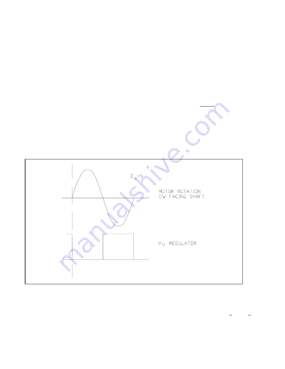
Figure 5-1. Pulse Output, One Revolution for a Two-Pole Machine.
5.
P
V
: Same as P
U
except Phase
2. Replace U with V in Figure.
6.
P
W
: Same as P
U
except
Phase 3. Replace U with W in
Figure.
The control can be programmed
for 4, 6, or 8 pole motors.
The encoder P
U
must be aligned
with E
U
-N motor voltage. The
neutral can be obtained by adding
three 10K resistors (>2 watts) to
601(U), 602(V), 603(W).
Erratic or no rotation can occur if
the encoder is not aligned
correctly or if it is faulty. The drive
also requires correct A, A, B and B
signals from the encoder for
proper operation.
Artisan Technology Group - Quality Instrumentation ... Guaranteed | (888) 88-SOURCE | www.artisantg.com


