49
WEIGHT
WEB
MOTOR
ROLL
Figure 42. Preloaded Dancer Loop Preceding Winder.
9. Adjust the current or speed limit:
With Speed Control models:
The maximum DC current output from the controller with CURRENT
LIMIT potentiometer set full CW is greater than 150%, possibly 200%
maximum, of the J5 armature current setting. If 150% of the J5
armature current is excessive for the application or if stress on the
driven equipment must be reduced, turn CURRENT LIMIT in the CCW
direction until adequate setting is obtained.
With Torque Control models:
D
With minimum load torque (motor disconnected or an empty winder
roll without web), turn the Torque potentiometer fully CW and SPD
LIM fully CCW.
D
Adjust speed limit with SPD LIM for maximum desired motor
application speed or 90/180 VDC on the armature.
D
Return the Torque potentiometer fully CCW.
10. Adjust the IR Comp:
With Speed Control models only:
If the torque demand on the
drive motor is relatively uniform, IR drop compensation is not
required. Turn IR DROP to zero (CCW).
On models employing DC tachometer speed feedback, the IR
Drop Compensation potentiometer should be set at zero, fully
CCW.
If the load torque is changing (i.e., a conveyor that can be empty
and then some time later loaded with material), the increased load
will cause a speed change. This speed change may be
compensated with IR DROP. (Fig 43) Turn IR DROP slightly CW
until this droop is minimized. After adjusting IR drop compensation
to minimize speed change with load the maximum and minimum
speed settings should be rechecked for proper settings. Note that
excessive IR drop compensation can cause motor instability and
hunting. A Tachometer should be used for better speed regulation.
Содержание DC2 VS series
Страница 1: ......
Страница 2: ......
Страница 3: ......
Страница 4: ......
Страница 5: ......
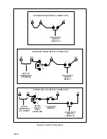
Страница 31: ...3 16 419 519 TB2 Motor Mounted D C Tachometer Figure 3 8 D C Tachometer Connection...
Страница 48: ...5 6 Figure 5 1 Wiring Diagram of Basic Speed Controller 0 57210 30...
Страница 49: ...5 7...
Страница 51: ...5 9 J4...
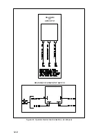
Страница 53: ...5 11 DEVICE INTERCONNECTIONS BACK OF REVERSING SWITCH Figure 5 3 Operator Device Interconnections...
Страница 56: ...Reliance Electric 24701 Euclid Avenue Cleveland Ohio 44117 216 266 7000 Printed in U S A D2 3231 3 March 1994...


