


48
With Speed Control models:
D
Use a handheld tachometer to monitor motor speed; or use a
multimeter to measure armature voltage, which is approximately
proportional to speed (115volt control: 90 VDC = 100% speed;
230volt control: 180 VDC = 100% speed).
D
Press the Start button and slowly turn the Speed potentiometer to
maximum (fully CW). The motor should run at about 50% of
maximum.
D
Slowly turn MAX CW until about 80% speed is reached.
D
Turn the Speed potentiometer fully CCW.
D
Turn MIN CW until the desired minimum speed is reached.
D
Since the MIN and MAX potentiometers interact, repeat the Speed
Control procedure until the desired maximum and minimum speeds
are reached.
With Torque Control models:
Torque control models must only be used when synchronizing this
driven machine section with other process machine sections on which
there is a drive that consistently and reliably establishes line speed.
D
Load the motor with a reasonably constant load over the speed
range. Such a system may be a pre loaded dancer loop preceding
a center driven winder. See Figure 42.
D
Provide a means of measuring torque, such as measuring armature
current. For example, for a 1 HP motor at 180 VDC rated at a
armature current of 5 amps and with a base speed of 1750 RPM:
1 HP X 5250
1750 RPM
= 3 ftlbs
Therefore, 5 amps equals 3 ftlbs.
D
Reestablish the torque load on the motor and load the motor to
maximum torque.
D
Press the Start button and slowly turn the Torque potentiometer to
maximum (fully CW).
D
Slowly turn SPD LIM potentiometer CW until measured torque no
longer increases.
D
Slowly turn MAX (CW) until the maximum desired torque is reached.
D
Turn the torque potentiometer fully CCW.
D
Slowly turn MIN CW until the minimum desired torque is reached.
D
Since the MIN and MAX potentiometers interact, repeat this Torque
Control procedure until the maximum and minimum torques are
reached.
Содержание DC2 VS series
Страница 1: ......
Страница 2: ......
Страница 3: ......
Страница 4: ......
Страница 5: ......
Страница 31: ...3 16 419 519 TB2 Motor Mounted D C Tachometer Figure 3 8 D C Tachometer Connection...
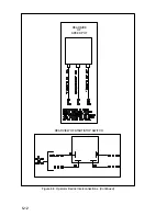
Страница 48: ...5 6 Figure 5 1 Wiring Diagram of Basic Speed Controller 0 57210 30...
Страница 49: ...5 7...
Страница 51: ...5 9 J4...
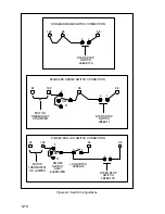
Страница 53: ...5 11 DEVICE INTERCONNECTIONS BACK OF REVERSING SWITCH Figure 5 3 Operator Device Interconnections...
Страница 56: ...Reliance Electric 24701 Euclid Avenue Cleveland Ohio 44117 216 266 7000 Printed in U S A D2 3231 3 March 1994...