36
45
O
45
O
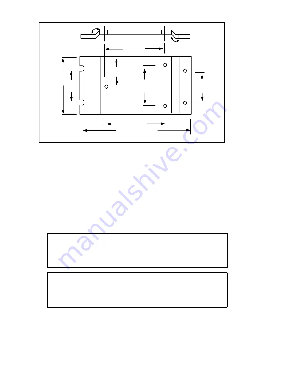
5.50"
6.25"
4.25"
3.29"
4.50"
6.50"
8.66"
4.25"
Figure 3.2C. HSI50 Heatsink Dimensions
Install the Motor
1. Verify that the motor is the appropriate rating to use with the
controller.
2. Install the DC motor in accordance with its own installation
instructions.
3. Make sure that coupled applications have proper shaft alignment
with the driven machine or that belted applications have proper
sheave/belt alignment to minimize unnecessary motor loading.
Install a Disconnect
DANGER
THIS EQUIPMENT IS AT LINE VOLTAGE WHEN AC POWER IS CONNECTED,
DISCONNECT AND LOCKOUT ALL UNGROUNDED CONDUCTORS OF THE
AC POWER LINE. FAILURE TO OBSERVE THESE PRECAUTIONS COULD
RESULT IN SEVERE BODILY INJURY OR LOSS OF LIFE.
DANGER
SOME DRIVE MODELS ARE NOT EQUIPPED WITH A FUSE AS STANDARD.
THE CUSTOMER MUST SUPPLY A CLASS J UL LISTED AND/OR CSA CERTI
FIED 20 AMP, 600 V TIMEDELAY FUSE. FAILURE TO OBSERVE THIS PRE
CAUTION COULD RESULT IN SEVERE BODILY INJURY OR LOSS OF LIFE.
Содержание DC2 VS series
Страница 1: ......
Страница 2: ......
Страница 3: ......
Страница 4: ......
Страница 5: ......
Страница 31: ...3 16 419 519 TB2 Motor Mounted D C Tachometer Figure 3 8 D C Tachometer Connection...
Страница 48: ...5 6 Figure 5 1 Wiring Diagram of Basic Speed Controller 0 57210 30...
Страница 49: ...5 7...
Страница 51: ...5 9 J4...
Страница 53: ...5 11 DEVICE INTERCONNECTIONS BACK OF REVERSING SWITCH Figure 5 3 Operator Device Interconnections...
Страница 56: ...Reliance Electric 24701 Euclid Avenue Cleveland Ohio 44117 216 266 7000 Printed in U S A D2 3231 3 March 1994...


