


Inserting and Extracting a Transceiver
6-4
SmartEdge 100 Router Hardware Guide
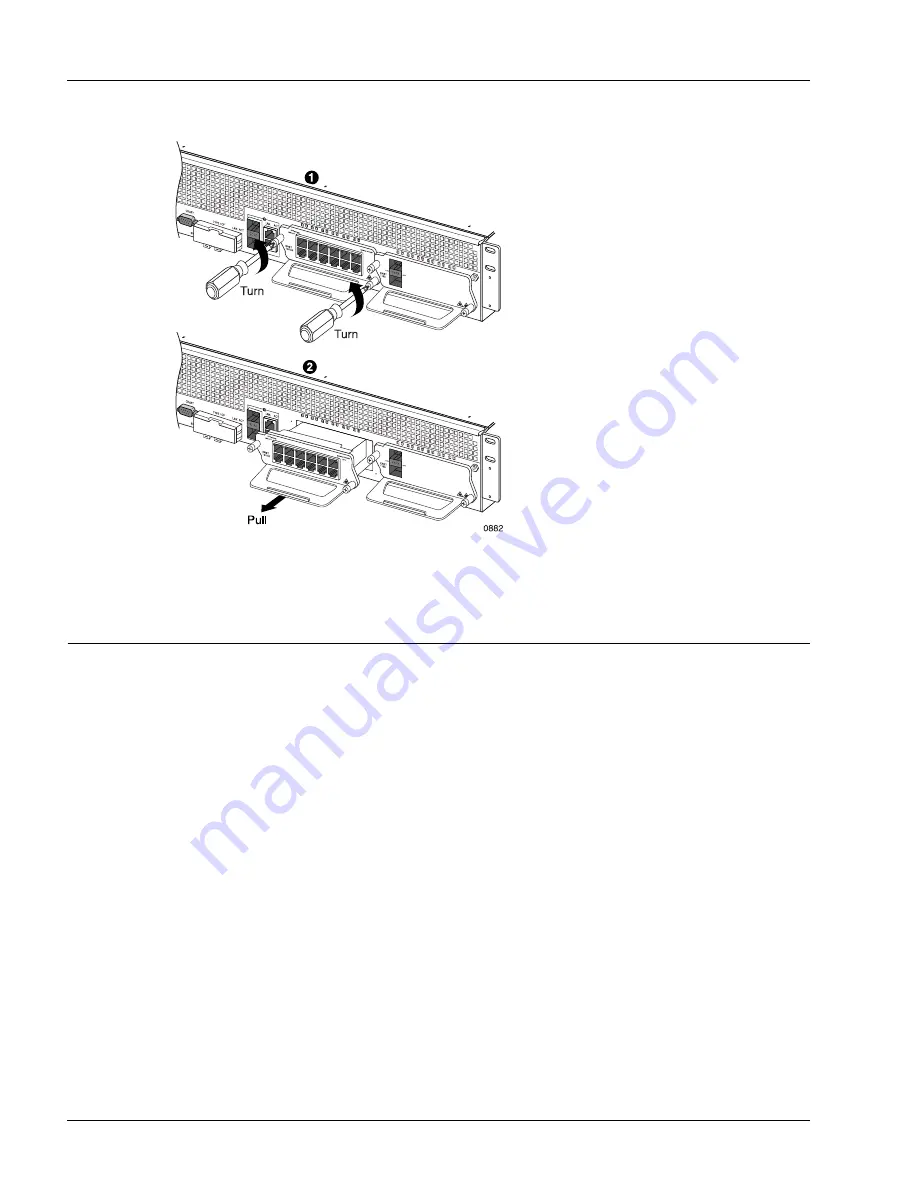
Figure 6-2
Extracting a MIC
Inserting and Extracting a Transceiver
Optical Fast Ethernet (FE) and optical Gigabit Ethernet (GE) ports require small form-factor pluggable
(SFP) transceiver in each port. Native ports, if configured as optical ports, also require an SFP transceiver
in each port.
To insert or extract a transceiver of any type, perform the appropriate procedure in the following sections;
these procedures are referenced in the installation and removal procedures for transceivers throughout this
chapter:
•
•
Содержание SmartEdge 100
Страница 4: ......
Страница 8: ...viii SmartEdge 100 Router Hardware Guide...
Страница 14: ...Ordering Documentation xiv SmartEdge 100 Router Hardware Guide...
Страница 52: ...Connecting and Routing the Cables 4 18 SmartEdge 100 Router Hardware Guide...
Страница 72: ...Obtaining Assistance 5 20 SmartEdge 100 Router Hardware Guide...
Страница 90: ...FE and GE MIC and Native Port Cables A 6 SmartEdge 100 Router Hardware Guide...
Страница 94: ...FE and GE Port Alarms B 4 SmartEdge 100 Router Hardware Guide...


