


3-12
5.
5.
5.
5.
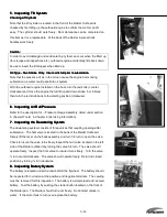
Inspecting Tilt System
Inspecting Tilt System
Inspecting Tilt System
Inspecting Tilt System
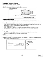
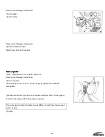
Checking Lift Cylinder
Checking Lift Cylinder
Checking Lift Cylinder
Checking Lift Cylinder
Note that the lift cylinder is located in the front of the Raider Outboard is
checked by first tilting up the outboard engine to confirm the motor can tilt
easy. The cylinder should work freely. No maintenance can be completed on
this item as it is a replaceable. At the back of the Raider insure all lock
handles work freely.
Ca
Ca
Ca
Caution:
ution:
ution:
ution:
In order to avoid damage and accidental injury that can occur when the tilted up
(for storage and inspections etc.) outboard engine accidentally tilts back down,
be use to insert the tilt stopper when tilted up.
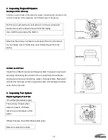
Oil Type
Oil Type
Oil Type
Oil Type Two Stroke Only. Insure oil is full prior to submersion.
Two Stroke Only. Insure oil is full prior to submersion.
Two Stroke Only. Insure oil is full prior to submersion.
Two Stroke Only. Insure oil is full prior to submersion.
Note that the presence of air in the oil can cause the engine harm during
submersion as water could penetrate oil system
With the outboard engine installed on the boat, turn the red knob (counter
clockwise) and move the engine the full tilt up and down stroke 5 or 6 times;
then turn the red knob back to the starting position (clockwise).
6.
6.
6.
6.
Inspecting Air Rail Pressure
Inspecting Air Rail Pressure
Inspecting Air Rail Pressure
Inspecting Air Rail Pressure
Refer to the description for ~ Pressure Gauge Assembly, listed under section
5. (Special Tools) in Chapter 2 (Servicing Information).
7.
7.
7.
7.
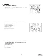
Inspecting the Dewatering System
Inspecting the Dewatering System
Inspecting the Dewatering System
Inspecting the Dewatering System
The dewatering system consists of three valves that requiring opening after
submersion. The first valve is located in the back of the Raider Outboard.
Simply lift the lever on the back assembly and turn 1/4 turn to open the valve.
Check to insure the valve turns freely.Inspect the mid valve located on the left
side of the Raider outboard by turning the valve 1/4 turn. The valve should
operate freely. Inspect the front valve to insure it turns freely. Turn the valve
⑮ turn counterclockwise. The valve should operate freely. Return to closed
position by turning ⑮ turn clockwise.
8.
8.
8.
8.
Inspecting Battery System
Inspecting Battery System
Inspecting Battery System
Inspecting Battery System
The battery is located under the cowl behind the flywheel. The battery should
be inspected for corrosion at the positive and negative terminals. The cowling
must be removed for this inspection. The battery is a simple lead acid, sealed,
battery. Test the battery by pushing the starter button located on the front of
the Raider pan. The Raider should turn over freely. Do not start unless in
water. If the motor fails to turn over replace the battery.
Содержание 40 hp
Страница 3: ......
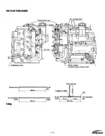
Страница 9: ...1 2 2 O 2 O 2 O 2 Outline Dimensions utline Dimensions utline Dimensions utline Dimensions ...
Страница 17: ...1 10 ...
Страница 19: ...2 2 ...
Страница 20: ...2 1 ...
Страница 35: ...2 16 5 Special Tools 5 Special Tools 5 Special Tools 5 Special Tools ...
Страница 43: ...2 24 ...
Страница 48: ...3 5 ...
Страница 50: ...3 7 ...
Страница 54: ...3 11 ...
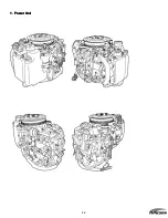
Страница 57: ...4 2 1 1 1 1 Power Uni Power Uni Power Uni Power Unit t t t ...
Страница 60: ...4 5 ...
Страница 66: ...4 11 ...
Страница 68: ...4 13 ...
Страница 72: ...4 17 ...
Страница 75: ...4 20 ...
Страница 86: ...4 31 ...
Страница 97: ...4 42 Piston and Crankshaft Piston and Crankshaft Piston and Crankshaft Piston and Crankshaft ...
Страница 106: ...4 51 ...
Страница 111: ...5 2 1 1 1 1 Wire Routing Wire Routing Wire Routing Wire Routing ...
Страница 112: ...5 3 ...
Страница 113: ...5 4 ...
Страница 114: ...5 5 ...
Страница 115: ...5 6 ...
Страница 116: ...5 7 Wiring Diagram 40B 50B EPTO ...
Страница 117: ...5 8 ...
Страница 118: ...5 9 ...
Страница 119: ...5 10 ...
Страница 120: ...5 11 ...
Страница 121: ...5 12 ...
Страница 126: ...5 17 Note Slash shows stripe color of cable 2 2 2 2 Assembly Assembly Assembly Assembly ...
Страница 127: ...5 18 Wiring around solenoid Bracket ...
Страница 128: ...5 19 ...
Страница 129: ...5 20 ...
Страница 130: ...5 21 ...
Страница 136: ...5 27 Kill Switch Crank Sensor Oil Level Sensor Grounds Air Injector 1 ...
Страница 137: ...5 28 Air Injector 2 Air Injector 3 Coil 1 Coil 2 Coil 3 ...
Страница 138: ...5 29 Fuel Pump Fuse Box Regulator Stator Complete Wiring harness ...
Страница 140: ...6 2 1 1 1 1 Configuration Configuration Configuration Configuration GEARCASE DRIVESHAFT ...
Страница 141: ...6 3 GEARCASE PROPELLERSHAFT ...
Страница 152: ...6 14 ...
Страница 153: ...6 15 ...
Страница 185: ...10 20 ...
Страница 193: ...11 8 ...