


7-4
3.
3.
3.
3.
Stopping RAIDER
Stopping RAIDER
Stopping RAIDER
Stopping RAIDER
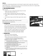
1.
Slow engine to idle speed.
2.
Move shift lever to NEUTRAL position.
3.
Press and hold stop button until the engine stops running.
a)
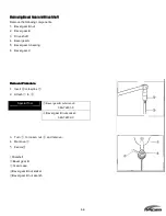
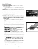
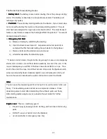
Trim Angle
Trim Angle
Trim Angle
Trim Angle Engine should be perpendicular to water when boat is
underway. This adjustment can only be determined by water testing the
boat. Set angle adjustment for NORMAL RIB load.
•
Move angle adjusting rod as required.
b)
Trailering
Trailering
Trailering
Trailering Place the engine in the normal vertical position. For additional
road clearance, move angle adjusting rod to an outer stern bracket
position. Refer to RAIDER Trim Angle.
o
DO NOT
DO NOT
DO NOT
DO NOT use the tilt support as a tailoring bracket.
c)
Tilting :
Tilting :
Tilting :
Tilting :DO NOT push down on tiller handle to tilt engine.
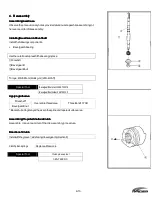
d)
Raise RAIDER
Raise RAIDER
Raise RAIDER
Raise RAIDER
1.
Move tilt/run lever to the TILT position.
2.
Use tilt grip on engine cover to raise engine to the full tilt position. Tilt
support will automatically engage.
While engine is tilted, leave tilt/run lever at TILT position. If lever is at RUN
position, the tilt support can release unexpectedly and allow engine to drop.
e)
Lower RAIDER
Lower RAIDER
Lower RAIDER
Lower RAIDER
1. Move tilt/run lever to RUN position.
2. Use tilt grip on engine cover and raise engine slightly to disengage tilt
support. Lower engine into RUN position.
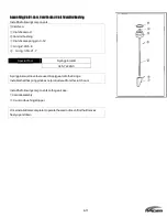
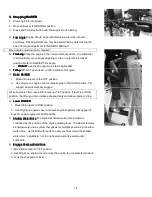
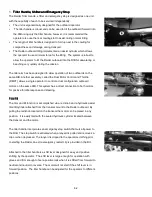
f)
Shallow W
Shallow W
Shallow W
Shallow Water Drive
ater Drive
ater Drive
ater Drive The engine's shallow water drive position is
controlled by the position of the angle adjusting lever. The Raider features
a shallow water drive system that allows for multiple positions for shallow
water drive. As the RIB with loads can vary we have made the shallow
water drive
“
adjustable
”
not in one fixed position like commercial
outboards.
g)
Engage Shallow Water Drive
Engage Shallow Water Drive
Engage Shallow Water Drive
Engage Shallow Water Drive
1. Move tilt/run lever to TILT position.
2. Use tilt grip on engine cover to raise the engine to your selected position.
3. Lock the engagement lever.
Содержание 40 hp
Страница 3: ......
Страница 9: ...1 2 2 O 2 O 2 O 2 Outline Dimensions utline Dimensions utline Dimensions utline Dimensions ...
Страница 17: ...1 10 ...
Страница 19: ...2 2 ...
Страница 20: ...2 1 ...
Страница 35: ...2 16 5 Special Tools 5 Special Tools 5 Special Tools 5 Special Tools ...
Страница 43: ...2 24 ...
Страница 48: ...3 5 ...
Страница 50: ...3 7 ...
Страница 54: ...3 11 ...
Страница 57: ...4 2 1 1 1 1 Power Uni Power Uni Power Uni Power Unit t t t ...
Страница 60: ...4 5 ...
Страница 66: ...4 11 ...
Страница 68: ...4 13 ...
Страница 72: ...4 17 ...
Страница 75: ...4 20 ...
Страница 86: ...4 31 ...
Страница 97: ...4 42 Piston and Crankshaft Piston and Crankshaft Piston and Crankshaft Piston and Crankshaft ...
Страница 106: ...4 51 ...
Страница 111: ...5 2 1 1 1 1 Wire Routing Wire Routing Wire Routing Wire Routing ...
Страница 112: ...5 3 ...
Страница 113: ...5 4 ...
Страница 114: ...5 5 ...
Страница 115: ...5 6 ...
Страница 116: ...5 7 Wiring Diagram 40B 50B EPTO ...
Страница 117: ...5 8 ...
Страница 118: ...5 9 ...
Страница 119: ...5 10 ...
Страница 120: ...5 11 ...
Страница 121: ...5 12 ...
Страница 126: ...5 17 Note Slash shows stripe color of cable 2 2 2 2 Assembly Assembly Assembly Assembly ...
Страница 127: ...5 18 Wiring around solenoid Bracket ...
Страница 128: ...5 19 ...
Страница 129: ...5 20 ...
Страница 130: ...5 21 ...
Страница 136: ...5 27 Kill Switch Crank Sensor Oil Level Sensor Grounds Air Injector 1 ...
Страница 137: ...5 28 Air Injector 2 Air Injector 3 Coil 1 Coil 2 Coil 3 ...
Страница 138: ...5 29 Fuel Pump Fuse Box Regulator Stator Complete Wiring harness ...
Страница 140: ...6 2 1 1 1 1 Configuration Configuration Configuration Configuration GEARCASE DRIVESHAFT ...
Страница 141: ...6 3 GEARCASE PROPELLERSHAFT ...
Страница 152: ...6 14 ...
Страница 153: ...6 15 ...
Страница 185: ...10 20 ...
Страница 193: ...11 8 ...