


7-2
Overview
Overview
Overview
Overview
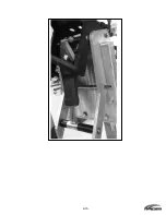
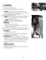
The Raider has a uniquely designed transom mount that allows the operator easier mounting of the outboard on the
Rubber Inflatable Boats. The design allows the motor to be slid over the transom and mounted even in high sea states.
This mount is lightweight and robust built for the Warfighter.
1.
1.
1.
1.
Motor Operating Instructions
Motor Operating Instructions
Motor Operating Instructions
Motor Operating Instructions
a)
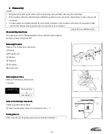
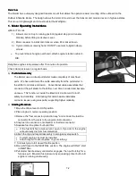
Motor Tilt Lock:
1)
Allow motor to drop to running position (against stop pin in transom
bracket) before lifting Lock down Lever.
2)
Motor is easier to install onto transom when tilt is locked down.
3)
Tighten clamp screws by hand. DO NOT use tools to tighten clamp
screws.
o
To prevent loss of engine overboard, attach engine retention cable to
RIB.
Retighten engine clamp screws after 15 minutes of operation.
Check clamp screws on a regular basis.
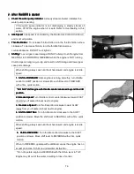
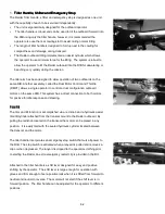
b)
Pull Start
Pull Start
Pull Start
Pull Start Assembly
Assembly
Assembly
Assembly
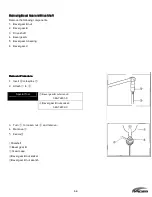
The Raider uses a robust pull starter made completely of machined
parts. We have eliminated the cable assembly from the pull starter to
the shifter to minimize corrosion. Conventional cable assemblies that
connected the pull starter to the shifter, over time corroded and became
an issue. This function is inside the Electronic Control unit for both
safety and reliability. Eliminating this cable besides eliminates
corrosion issues (using less parts) supporting higher reliability.
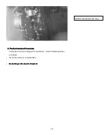
c)
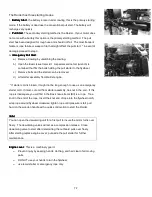
Starting Procedure
Starting Procedure
Starting Procedure
Starting Procedure
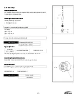
1.
Move the tilt/run lever to RUN position.
2.
Place engine in normal operating position.
3.
Remove the "fuel connector protection cap" and connect the fuel line
connector from the tank to the engine’s fuel connector.
4.
Snap fuel line connector onto bladder or fuel tank connector.
5.
Squeeze fuel line primer bulb until firm.
o
If the fuel tank has a manual vent, open it. If you don't, the engine
will eventually die from fuel starvation)
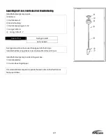
6.
Attach the clip and lanyard assembly to emergency stop switch.
•
To start engine, clip must be installed.
•
Attach lanyard to secure place on your clothing.
7.
Turn twist grip to full closed throttle position.
8.
Move shift lever to the NEUTRAL position. The engine will ONLY start
in NEUTRAL.
9.
Pull starter handle slowly until starter engages, then pull forcibly for a
full rope pull. Maintain fuel pressure by squeezing primer bulb until
engine is running continuously.
Содержание 40 hp
Страница 3: ......
Страница 9: ...1 2 2 O 2 O 2 O 2 Outline Dimensions utline Dimensions utline Dimensions utline Dimensions ...
Страница 17: ...1 10 ...
Страница 19: ...2 2 ...
Страница 20: ...2 1 ...
Страница 35: ...2 16 5 Special Tools 5 Special Tools 5 Special Tools 5 Special Tools ...
Страница 43: ...2 24 ...
Страница 48: ...3 5 ...
Страница 50: ...3 7 ...
Страница 54: ...3 11 ...
Страница 57: ...4 2 1 1 1 1 Power Uni Power Uni Power Uni Power Unit t t t ...
Страница 60: ...4 5 ...
Страница 66: ...4 11 ...
Страница 68: ...4 13 ...
Страница 72: ...4 17 ...
Страница 75: ...4 20 ...
Страница 86: ...4 31 ...
Страница 97: ...4 42 Piston and Crankshaft Piston and Crankshaft Piston and Crankshaft Piston and Crankshaft ...
Страница 106: ...4 51 ...
Страница 111: ...5 2 1 1 1 1 Wire Routing Wire Routing Wire Routing Wire Routing ...
Страница 112: ...5 3 ...
Страница 113: ...5 4 ...
Страница 114: ...5 5 ...
Страница 115: ...5 6 ...
Страница 116: ...5 7 Wiring Diagram 40B 50B EPTO ...
Страница 117: ...5 8 ...
Страница 118: ...5 9 ...
Страница 119: ...5 10 ...
Страница 120: ...5 11 ...
Страница 121: ...5 12 ...
Страница 126: ...5 17 Note Slash shows stripe color of cable 2 2 2 2 Assembly Assembly Assembly Assembly ...
Страница 127: ...5 18 Wiring around solenoid Bracket ...
Страница 128: ...5 19 ...
Страница 129: ...5 20 ...
Страница 130: ...5 21 ...
Страница 136: ...5 27 Kill Switch Crank Sensor Oil Level Sensor Grounds Air Injector 1 ...
Страница 137: ...5 28 Air Injector 2 Air Injector 3 Coil 1 Coil 2 Coil 3 ...
Страница 138: ...5 29 Fuel Pump Fuse Box Regulator Stator Complete Wiring harness ...
Страница 140: ...6 2 1 1 1 1 Configuration Configuration Configuration Configuration GEARCASE DRIVESHAFT ...
Страница 141: ...6 3 GEARCASE PROPELLERSHAFT ...
Страница 152: ...6 14 ...
Страница 153: ...6 15 ...
Страница 185: ...10 20 ...
Страница 193: ...11 8 ...