


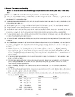


1-5
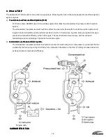
c)
ECU Control
ECU Control
ECU Control
ECU Control
With TLDI, a network of connected sensors enables the Engine Control Unit (ECU) to precisely regulate fuel
mixture, injection rate and ignition timing. The ECU also uses a stratified fuel feed process to provide lean
combustion in the low-speed range, while utilizing more homogenized change to ensure the fuel mixture is
distributed uniformly throughout the combustion chamber when operating in the high-speed range to ensure
maximum combustion efficiency.
Below is a block diagram of the Engine Control Unit that allows the Raider 50 horsepower outboard to function as
a multi-fuel engine.
Input Control
Input Control
Input Control
Input Control
(Sensor/Switch)
Control
Control
Control
Control
(ECU)
Output
Output
Output
Output
(Actuator)
Throttle-Position Sensor
(TPS)
#1, #2 
Fuel injectors
Crank-Position Sensor
(CPS)
#1, #2 
Air injectors
Water-
Temperature
Sensor
#1, #2 
Ignition coils
Oil level Sensor
Fuel Selector
Capacitor
Warning indicators
De-Watering Pull
Warning oil
Stop Switch
Engine Control
Unit
(ECU)
Fuel-feed pump (FFP)
Note: All warning indicators have been silenced on the Raider to not compromise missions.
RAIDER has also integrated a series of mechanical valves into the TLDI to remove water from the system after
submersion. These valves are detailed in detail in Chapter 7.
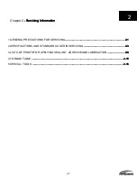
Содержание 40 hp
Страница 3: ......
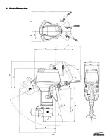
Страница 9: ...1 2 2 O 2 O 2 O 2 Outline Dimensions utline Dimensions utline Dimensions utline Dimensions ...
Страница 17: ...1 10 ...
Страница 19: ...2 2 ...
Страница 20: ...2 1 ...
Страница 35: ...2 16 5 Special Tools 5 Special Tools 5 Special Tools 5 Special Tools ...
Страница 43: ...2 24 ...
Страница 48: ...3 5 ...
Страница 50: ...3 7 ...
Страница 54: ...3 11 ...
Страница 57: ...4 2 1 1 1 1 Power Uni Power Uni Power Uni Power Unit t t t ...
Страница 60: ...4 5 ...
Страница 66: ...4 11 ...
Страница 68: ...4 13 ...
Страница 72: ...4 17 ...
Страница 75: ...4 20 ...
Страница 86: ...4 31 ...
Страница 97: ...4 42 Piston and Crankshaft Piston and Crankshaft Piston and Crankshaft Piston and Crankshaft ...
Страница 106: ...4 51 ...
Страница 111: ...5 2 1 1 1 1 Wire Routing Wire Routing Wire Routing Wire Routing ...
Страница 112: ...5 3 ...
Страница 113: ...5 4 ...
Страница 114: ...5 5 ...
Страница 115: ...5 6 ...
Страница 116: ...5 7 Wiring Diagram 40B 50B EPTO ...
Страница 117: ...5 8 ...
Страница 118: ...5 9 ...
Страница 119: ...5 10 ...
Страница 120: ...5 11 ...
Страница 121: ...5 12 ...
Страница 126: ...5 17 Note Slash shows stripe color of cable 2 2 2 2 Assembly Assembly Assembly Assembly ...
Страница 127: ...5 18 Wiring around solenoid Bracket ...
Страница 128: ...5 19 ...
Страница 129: ...5 20 ...
Страница 130: ...5 21 ...
Страница 136: ...5 27 Kill Switch Crank Sensor Oil Level Sensor Grounds Air Injector 1 ...
Страница 137: ...5 28 Air Injector 2 Air Injector 3 Coil 1 Coil 2 Coil 3 ...
Страница 138: ...5 29 Fuel Pump Fuse Box Regulator Stator Complete Wiring harness ...
Страница 140: ...6 2 1 1 1 1 Configuration Configuration Configuration Configuration GEARCASE DRIVESHAFT ...
Страница 141: ...6 3 GEARCASE PROPELLERSHAFT ...
Страница 152: ...6 14 ...
Страница 153: ...6 15 ...
Страница 185: ...10 20 ...
Страница 193: ...11 8 ...