


1-7
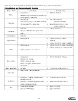
4.Fuel Supply System
4.Fuel Supply System
4.Fuel Supply System
4.Fuel Supply System
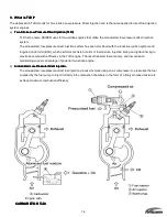
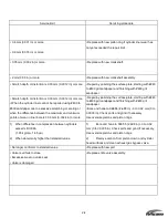
Starting the engine activates the fuel pump (3), which draws fuel from the fuel tank (1) and routes it through the fuel filter
(2) to the vapor separator (4). The fuel is pressurized in the fuel-feed pump (FFP) (5); then passes through the high-
pressure filter (6) to the air rail (7), from there it is injected into the combustion chambers. The fuel regulator (8) regulates
fuel pressure so as to keep it 70 kPa (10 psi)higher than the pressurized air pressure (55OkPa Bopsi)to inject fuel into
combustion chamber after overcoming the air pressure mentioned in Air supply system as follows. Any excess fuelis
depressurized and diverted through the FFP case (9) and back to the vapor separator (4). The returned fuel contains air
bubbles left over from being pressurized at (5). These bleed from the top of the vapor separator (4) to the throttle body
(10) and is fed to the air intake system.
Содержание 40 hp
Страница 3: ......
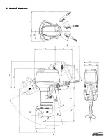
Страница 9: ...1 2 2 O 2 O 2 O 2 Outline Dimensions utline Dimensions utline Dimensions utline Dimensions ...
Страница 17: ...1 10 ...
Страница 19: ...2 2 ...
Страница 20: ...2 1 ...
Страница 35: ...2 16 5 Special Tools 5 Special Tools 5 Special Tools 5 Special Tools ...
Страница 43: ...2 24 ...
Страница 48: ...3 5 ...
Страница 50: ...3 7 ...
Страница 54: ...3 11 ...
Страница 57: ...4 2 1 1 1 1 Power Uni Power Uni Power Uni Power Unit t t t ...
Страница 60: ...4 5 ...
Страница 66: ...4 11 ...
Страница 68: ...4 13 ...
Страница 72: ...4 17 ...
Страница 75: ...4 20 ...
Страница 86: ...4 31 ...
Страница 97: ...4 42 Piston and Crankshaft Piston and Crankshaft Piston and Crankshaft Piston and Crankshaft ...
Страница 106: ...4 51 ...
Страница 111: ...5 2 1 1 1 1 Wire Routing Wire Routing Wire Routing Wire Routing ...
Страница 112: ...5 3 ...
Страница 113: ...5 4 ...
Страница 114: ...5 5 ...
Страница 115: ...5 6 ...
Страница 116: ...5 7 Wiring Diagram 40B 50B EPTO ...
Страница 117: ...5 8 ...
Страница 118: ...5 9 ...
Страница 119: ...5 10 ...
Страница 120: ...5 11 ...
Страница 121: ...5 12 ...
Страница 126: ...5 17 Note Slash shows stripe color of cable 2 2 2 2 Assembly Assembly Assembly Assembly ...
Страница 127: ...5 18 Wiring around solenoid Bracket ...
Страница 128: ...5 19 ...
Страница 129: ...5 20 ...
Страница 130: ...5 21 ...
Страница 136: ...5 27 Kill Switch Crank Sensor Oil Level Sensor Grounds Air Injector 1 ...
Страница 137: ...5 28 Air Injector 2 Air Injector 3 Coil 1 Coil 2 Coil 3 ...
Страница 138: ...5 29 Fuel Pump Fuse Box Regulator Stator Complete Wiring harness ...
Страница 140: ...6 2 1 1 1 1 Configuration Configuration Configuration Configuration GEARCASE DRIVESHAFT ...
Страница 141: ...6 3 GEARCASE PROPELLERSHAFT ...
Страница 152: ...6 14 ...
Страница 153: ...6 15 ...
Страница 185: ...10 20 ...
Страница 193: ...11 8 ...