


2-19
2.
2.
2.
2.
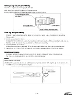
Using the Special Tool
Using the Special Tool
Using the Special Tool
Using the Special Tool
Pressure Gage Assembly
Pressure Gage Assembly
Pressure Gage Assembly
Pressure Gage Assembly
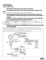
Measuring Fuel and Air Pressure
1.
Mover the lever for cock (3T5
Mover the lever for cock (3T5
Mover the lever for cock (3T5
Mover the lever for cock (3T5----72883
72883
72883
72883----O) to position A shown in the figure below.
O) to position A shown in the figure below.
O) to position A shown in the figure below.
O) to position A shown in the figure below.
2.
Screw adapt
Screw adapt
Screw adapt
Screw adapter B (3T5
er B (3T5
er B (3T5
er B (3T5----72884
72884
72884
72884----0) into either the air or fuel pressure measuring valves located on the air rail.
0) into either the air or fuel pressure measuring valves located on the air rail.
0) into either the air or fuel pressure measuring valves located on the air rail.
0) into either the air or fuel pressure measuring valves located on the air rail.
Caution:
Caution:
Caution:
Caution:
A small amount of fuel will spurt out as the adapter is inserted in the fuel measuring valve.
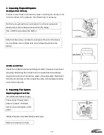
3.
With the ignition key set the OFF position, turn it to
With the ignition key set the OFF position, turn it to
With the ignition key set the OFF position, turn it to
With the ignition key set the OFF position, turn it to START to activate the starter motor and turn over the
START to activate the starter motor and turn over the
START to activate the starter motor and turn over the
START to activate the starter motor and turn over the
engine for approximately 15 seconds. (Once the engine starts, allow it to idle at 700 rpm for approximately for
engine for approximately 15 seconds. (Once the engine starts, allow it to idle at 700 rpm for approximately for
engine for approximately 15 seconds. (Once the engine starts, allow it to idle at 700 rpm for approximately for
engine for approximately 15 seconds. (Once the engine starts, allow it to idle at 700 rpm for approximately for
15 minutes.)
15 minutes.)
15 minutes.)
15 minutes.)
4.
If both fuel and air pressure values fall within the standard (rated) range,
If both fuel and air pressure values fall within the standard (rated) range,
If both fuel and air pressure values fall within the standard (rated) range,
If both fuel and air pressure values fall within the standard (rated) range, engine operation is
engine operation is
engine operation is
engine operation is
normal. (If not,
normal. (If not,
normal. (If not,
normal. (If not,
service the engine by referring to the relevant sections in this manual.)
service the engine by referring to the relevant sections in this manual.)
service the engine by referring to the relevant sections in this manual.)
service the engine by referring to the relevant sections in this manual.)
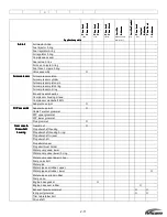
PRESSURE
Rated value (kPa, psi)
Rated range (kPa, psi)
Remarks
AIR PRESSURE
550, 80
550
④
30, 80
④
4
FUEL PRESSURE
620, 90
620
④
30, 90④ 4
Pressure falls when engine stops turning
over.
5.
When finished measuring, turn the lever to position B (open) to relieve internal pressure
When finished measuring, turn the lever to position B (open) to relieve internal pressure
When finished measuring, turn the lever to position B (open) to relieve internal pressure
When finished measuring, turn the lever to position B (open) to relieve internal pressure;;;; then remove adapter
then remove adapter
then remove adapter
then remove adapter
B from the measuring valve.
B from the measuring valve.
B from the measuring valve.
B from the measuring valve.
It is important to have a container handy. Once fuel measuring completes and the lever is set to position B (open), a
certain amount of fuel will spurt out from the hose (98AB-5-0200). Be sure to point the hose (98AH-8-1 000) on the cock
side lower than valve position and drain all remaining fuel prior to removing adapter B.
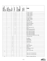
Содержание 40 hp
Страница 3: ......
Страница 9: ...1 2 2 O 2 O 2 O 2 Outline Dimensions utline Dimensions utline Dimensions utline Dimensions ...
Страница 17: ...1 10 ...
Страница 19: ...2 2 ...
Страница 20: ...2 1 ...
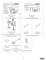
Страница 35: ...2 16 5 Special Tools 5 Special Tools 5 Special Tools 5 Special Tools ...
Страница 43: ...2 24 ...
Страница 48: ...3 5 ...
Страница 50: ...3 7 ...
Страница 54: ...3 11 ...
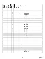
Страница 57: ...4 2 1 1 1 1 Power Uni Power Uni Power Uni Power Unit t t t ...
Страница 60: ...4 5 ...
Страница 66: ...4 11 ...
Страница 68: ...4 13 ...
Страница 72: ...4 17 ...
Страница 75: ...4 20 ...
Страница 86: ...4 31 ...
Страница 97: ...4 42 Piston and Crankshaft Piston and Crankshaft Piston and Crankshaft Piston and Crankshaft ...
Страница 106: ...4 51 ...
Страница 111: ...5 2 1 1 1 1 Wire Routing Wire Routing Wire Routing Wire Routing ...
Страница 112: ...5 3 ...
Страница 113: ...5 4 ...
Страница 114: ...5 5 ...
Страница 115: ...5 6 ...
Страница 116: ...5 7 Wiring Diagram 40B 50B EPTO ...
Страница 117: ...5 8 ...
Страница 118: ...5 9 ...
Страница 119: ...5 10 ...
Страница 120: ...5 11 ...
Страница 121: ...5 12 ...
Страница 126: ...5 17 Note Slash shows stripe color of cable 2 2 2 2 Assembly Assembly Assembly Assembly ...
Страница 127: ...5 18 Wiring around solenoid Bracket ...
Страница 128: ...5 19 ...
Страница 129: ...5 20 ...
Страница 130: ...5 21 ...
Страница 136: ...5 27 Kill Switch Crank Sensor Oil Level Sensor Grounds Air Injector 1 ...
Страница 137: ...5 28 Air Injector 2 Air Injector 3 Coil 1 Coil 2 Coil 3 ...
Страница 138: ...5 29 Fuel Pump Fuse Box Regulator Stator Complete Wiring harness ...
Страница 140: ...6 2 1 1 1 1 Configuration Configuration Configuration Configuration GEARCASE DRIVESHAFT ...
Страница 141: ...6 3 GEARCASE PROPELLERSHAFT ...
Страница 152: ...6 14 ...
Страница 153: ...6 15 ...
Страница 185: ...10 20 ...
Страница 193: ...11 8 ...