


10-17
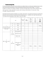
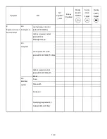
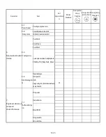
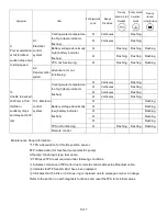
Symptom
Item
Self
-
diagnosable
points
Beeps
Disabled
Warning
indicator A (oil)
Disabled
Warning indicator
8 (watertemp)
Disabled
Warning
indicator
(battery)Disabled
0
Continuous
Flashing
Cooling water temperature
too high (temp.indicator
flashes)
0
Continuous
Flashing
0
Flashing
Flashing
Flashing
Battery voltage abnormally
high (battery
indicator
flashes)
0
Flashing
Flashing
Flashing
9-1.
Electrical
control
system
TPS not functioning
0
Flashing
Flashing
Flashing
9.
Poor acceleration
at full throttle or
sudden drop down
to idling speed
9-2.
Remote control
system
Advancer arm not
functioning
0
Continuous
Flashing
0
Continuous
Flashing
0
Continuous
Flashing
Cooling water temperature
too high (temp.indicator
flashes)
0
Continuous
Flashing
0
Flashing
0
Flashing
0
Flashing
0
Flashing
Battery voltage abnormally
low (battery indicator
flashes)
0
Flashing
TPS not functioning
0
Flashing
Flashing
Flashing
10.
Unable to exceed
3000 rpm at full
throttle or
suddenly drops
and stay sat 3000
rpm
10-1
.
Electrical
control
system
Remote control
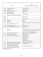
Maintenance Shop Information:
*1.TPS: abbreviation for throttle position sensor.
FFP: abbreviation for fuel-feed pump (electric pump)
Lift pump: diaphragm type fuel pump.
*2.TPSreset:TPS reset required under following conditions.
Indicates occurrence of TPS error due to remote control cable setup.Readjust cable.
Indicates that TPS and/or ECU have been replaced.
Indicates that the link or rod snap ring is replaced due to warpage or wear in linkage.
Refer to the section on self-diagnosis functions and reset theTPS to its initial values.
Содержание 40 hp
Страница 3: ......
Страница 9: ...1 2 2 O 2 O 2 O 2 Outline Dimensions utline Dimensions utline Dimensions utline Dimensions ...
Страница 17: ...1 10 ...
Страница 19: ...2 2 ...
Страница 20: ...2 1 ...
Страница 35: ...2 16 5 Special Tools 5 Special Tools 5 Special Tools 5 Special Tools ...
Страница 43: ...2 24 ...
Страница 48: ...3 5 ...
Страница 50: ...3 7 ...
Страница 54: ...3 11 ...
Страница 57: ...4 2 1 1 1 1 Power Uni Power Uni Power Uni Power Unit t t t ...
Страница 60: ...4 5 ...
Страница 66: ...4 11 ...
Страница 68: ...4 13 ...
Страница 72: ...4 17 ...
Страница 75: ...4 20 ...
Страница 86: ...4 31 ...
Страница 97: ...4 42 Piston and Crankshaft Piston and Crankshaft Piston and Crankshaft Piston and Crankshaft ...
Страница 106: ...4 51 ...
Страница 111: ...5 2 1 1 1 1 Wire Routing Wire Routing Wire Routing Wire Routing ...
Страница 112: ...5 3 ...
Страница 113: ...5 4 ...
Страница 114: ...5 5 ...
Страница 115: ...5 6 ...
Страница 116: ...5 7 Wiring Diagram 40B 50B EPTO ...
Страница 117: ...5 8 ...
Страница 118: ...5 9 ...
Страница 119: ...5 10 ...
Страница 120: ...5 11 ...
Страница 121: ...5 12 ...
Страница 126: ...5 17 Note Slash shows stripe color of cable 2 2 2 2 Assembly Assembly Assembly Assembly ...
Страница 127: ...5 18 Wiring around solenoid Bracket ...
Страница 128: ...5 19 ...
Страница 129: ...5 20 ...
Страница 130: ...5 21 ...
Страница 136: ...5 27 Kill Switch Crank Sensor Oil Level Sensor Grounds Air Injector 1 ...
Страница 137: ...5 28 Air Injector 2 Air Injector 3 Coil 1 Coil 2 Coil 3 ...
Страница 138: ...5 29 Fuel Pump Fuse Box Regulator Stator Complete Wiring harness ...
Страница 140: ...6 2 1 1 1 1 Configuration Configuration Configuration Configuration GEARCASE DRIVESHAFT ...
Страница 141: ...6 3 GEARCASE PROPELLERSHAFT ...
Страница 152: ...6 14 ...
Страница 153: ...6 15 ...
Страница 185: ...10 20 ...
Страница 193: ...11 8 ...